Fuel injection system which uses a pressure step-up unit

a technology of pressure step-up unit and fuel injection system, which is applied in the direction of fuel injection apparatus, machine/engine, feed system, etc., can solve the problems of valve member stroke, lack of flexibility of injection, and poor quantity tolerance in the metering of small fuel quantities

Inactive Publication Date: 2002-09-24
ROBERT BOSCH GMBH
View PDF9 Cites 95 Cited by
  • Summary
  • Abstract
  • Description
  • Claims
  • Application Information

AI Technical Summary

Problems solved by technology

A pressure reduction inside the control chamber causes a stroke of the valve member.
The disadvantage of these pressure-stepped-up systems resides in a lack of flexibility of the injection and poor quantity tolerance in the ...

Method used


Image

  • Fuel injection system which uses a pressure step-up unit
  • Fuel injection system which uses a pressure step-up unit
  • Fuel injection system which uses a pressure step-up unit

Examples


Embodiment Construction

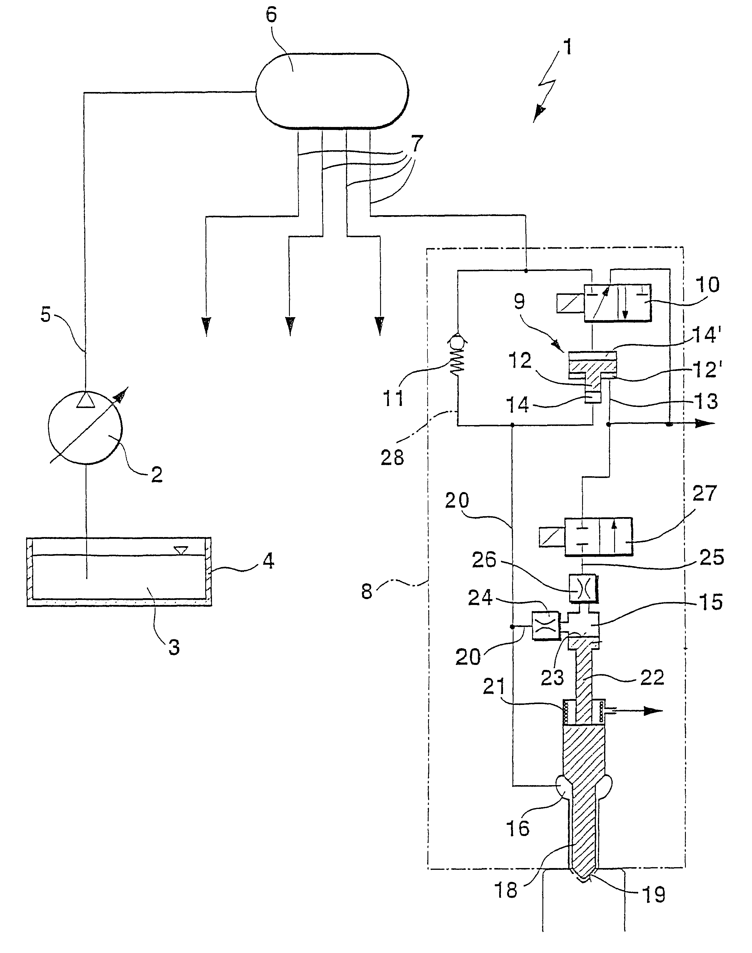
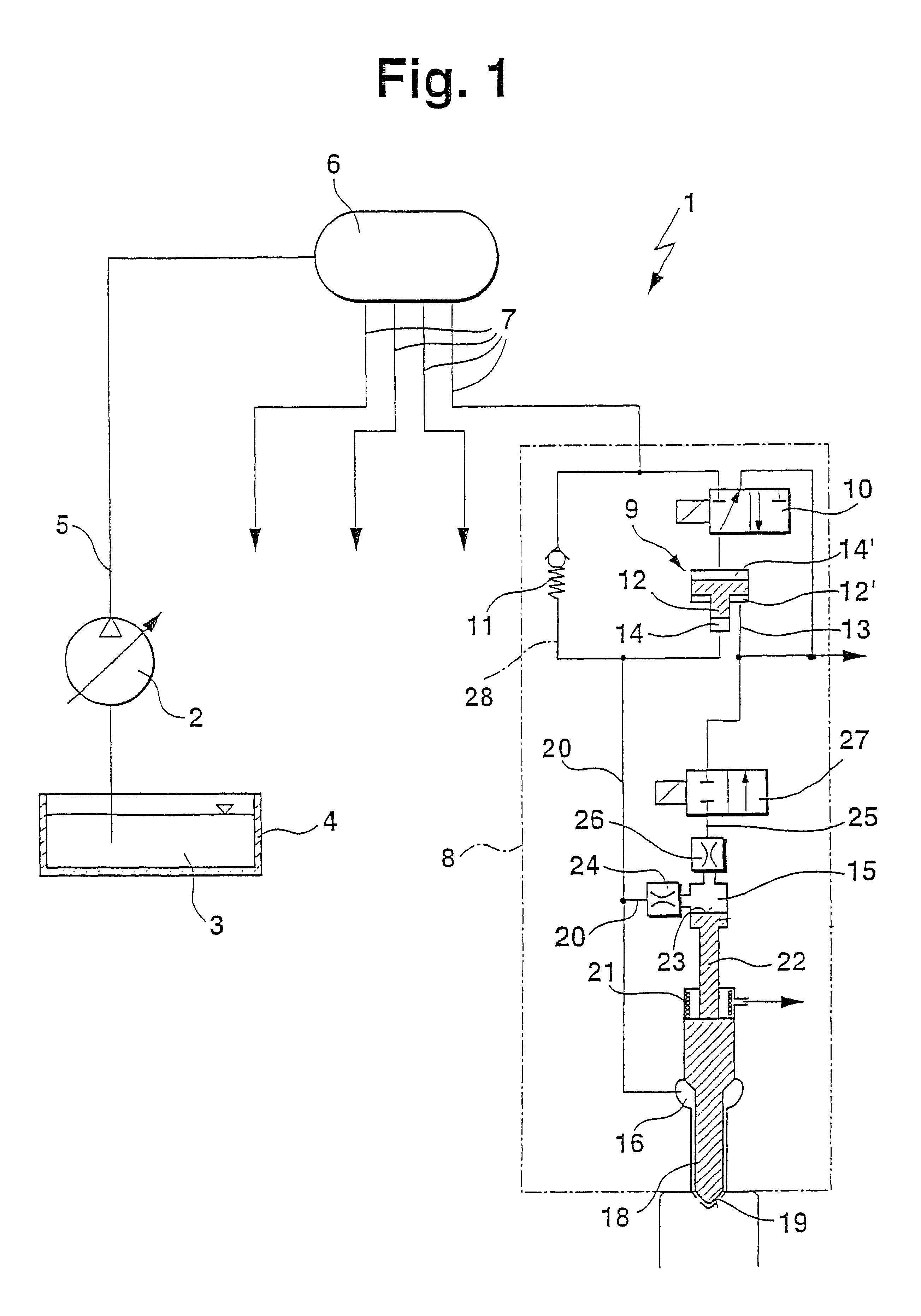
In the first exemplary embodiment, shown in FIG. 1, of a stroke-controlled fuel injection system 1, a quantity-regulated fuel pump 2 pumps fuel 3 out of a tank 4 via a supply line 5 into a central pressure storage chamber 6 (common rail), from which a plurality of pressure lines 7, corresponding in number to the number of individual cylinders, communicate to the individual injectors 8 (injection devices) protruding into the combustion chambers of the internal combustion engine to be supplied. In FIG. 1, only one of the injectors 8 is shown. With the aid of the fuel pump 2, a first system pressure is generated and stored in the pressure storage chamber 6. This first system pressure is used for preinjection and as needed for postinjection (HC enrichment for exhaust gas posttreatment or soot reduction) and for representing an injection course with a plateau, known as boot injection. For injection of fuel with a second, higher system pressure, each injector 8 is assigned a local pressur...


PUM


Abstract

A fuel injection system has a pressure step-up unit, disposed between a pressure storage chamber and a nozzle chamber, whose pressure chamber communicates with the nozzle chamber via a pressure line. A bypass line connected to the pressure storage chamber is also provided. The bypass line communicates directly with the pressure line. The bypass line can be used for pressure injection and is disposed parallel to the pressure chamber, so that the bypass line is open regardless of the motion and position of a displaceable piston element in the pressure step-up unit. This enhances the flexibility of injection.

Description

PRIOR ARTThe invention relates to a fuel injection system having a pressure step-up unit.For the sake of better comprehension of the specification and claims, some terms will first be defined: The fuel injection system of the invention can be embodied as either a stroke-controlled or a pressure-controlled fuel injection system. Within the scope of the invention, the term stroke-controlled fuel injection system will be understood to mean that the opening and closing of the injection opening is effected with the aid of a displaceable valve member on the basis of the hydraulic cooperation of the fuel pressures in a nozzle chamber and a control chamber. A pressure reduction inside the control chamber causes a stroke of the valve member. Alternatively, the excursion of the valve member can be effected by a final control element. In a pressure-controlled fuel injection system according to the invention, as a result of the fuel pressure prevailing in the nozzle chamber of an injector, the ...

Claims


Application Information

Patent Timeline
IPC IPC(8): F02M63/02F02M57/00F02M63/00F02M59/10F02M57/02F02M59/00F02M47/02F02M47/00F02M55/00F02M55/02
CPCF02M47/027F02M57/025F02M59/105F02M63/0225F02M2200/21F02M59/10
Inventor MAHR, BERNDKROPP, MARTINMAGEL, HANS-CHRISTOPHOTTERBACH, WOLFGANG
Owner ROBERT BOSCH GMBH
Why Eureka
Try Eureka