Noise reduction mechanism of fan device and molding method of porous damping material therefor

a technology of fan device and damping material, which is applied in the direction of machines/engines, liquid fuel engines, transportation and packaging, etc., can solve the problems of jet noise, high-frequency impulsive sound generation, and inability to effectively reduce the overall nois

Inactive Publication Date: 2002-09-24
KOMATSU LTD
View PDF10 Cites 93 Cited by
  • Summary
  • Abstract
  • Description
  • Claims
  • Application Information

AI Technical Summary

Benefits of technology

Accordingly, both of the impulsive sound and the jet noise can be effectively damped and the noise between the end of the fan and the fan shroud can be securely decreased.
As mentioned above, according to the above arrangement, since the size of the die required for molding can be reduced, thus reducing die cost and facilitating transportation and storage of the porous member.

Problems solved by technology

A strong swirl is generated at a slight gap between an end of the fan and the fan shroud in accordance with rotation of the fan, which causes jet noise.
However, according to the noise damper disclosed in the publications, since the perforated metal is used at the portion where the strong swirl is generated, high-frequency impulsive sound can be generated by an impact caused when the cooling air bumps into step portion of the through-holes of the perforated metal.
Accordingly, though the noise damper can reduce the jet noise, the impulsive sound can be newly generated, thus being unable to effectively reduce the overall noise.
Further, since the conventional perforated metal is not used, the cooling air does not bump into the hard step portion, thus being unlikely to generate impulsive sound.
However, a lot of trouble is required for cutting the porous damping material into a desired shape by the above-described cutting machine.
Further, it is not economical to form the fan shroud into a shape considering the fan performance such as the bell-mouth shape.
This is because, for instance, when the fan shroud is made of metal, great die cost is necessary on account of large size press die and, when the fan shroud is made of resin, the size of the molding die is enlarged and cost thereof is significant.
On the other hand, since the porous damping material directly confronts the fan, the porous damping material can be deteriorated or damaged by colliding with dust or rainwater snapped by the fan, thus deteriorating weather-resistance and durability of the porous damping material.
However, attachment work of the resin sheet or the cloth sheet onto the surface of the porous damping material by adhesion or thermal bonding is not easy and requires a lot of work, thus deteriorating productivity.

Method used


Image

  • Noise reduction mechanism of fan device and molding method of porous damping material therefor
  • Noise reduction mechanism of fan device and molding method of porous damping material therefor
  • Noise reduction mechanism of fan device and molding method of porous damping material therefor

Examples


first embodiment

[First Embodiment]

First embodiment of the present invention will be described below with reference to attached drawings.

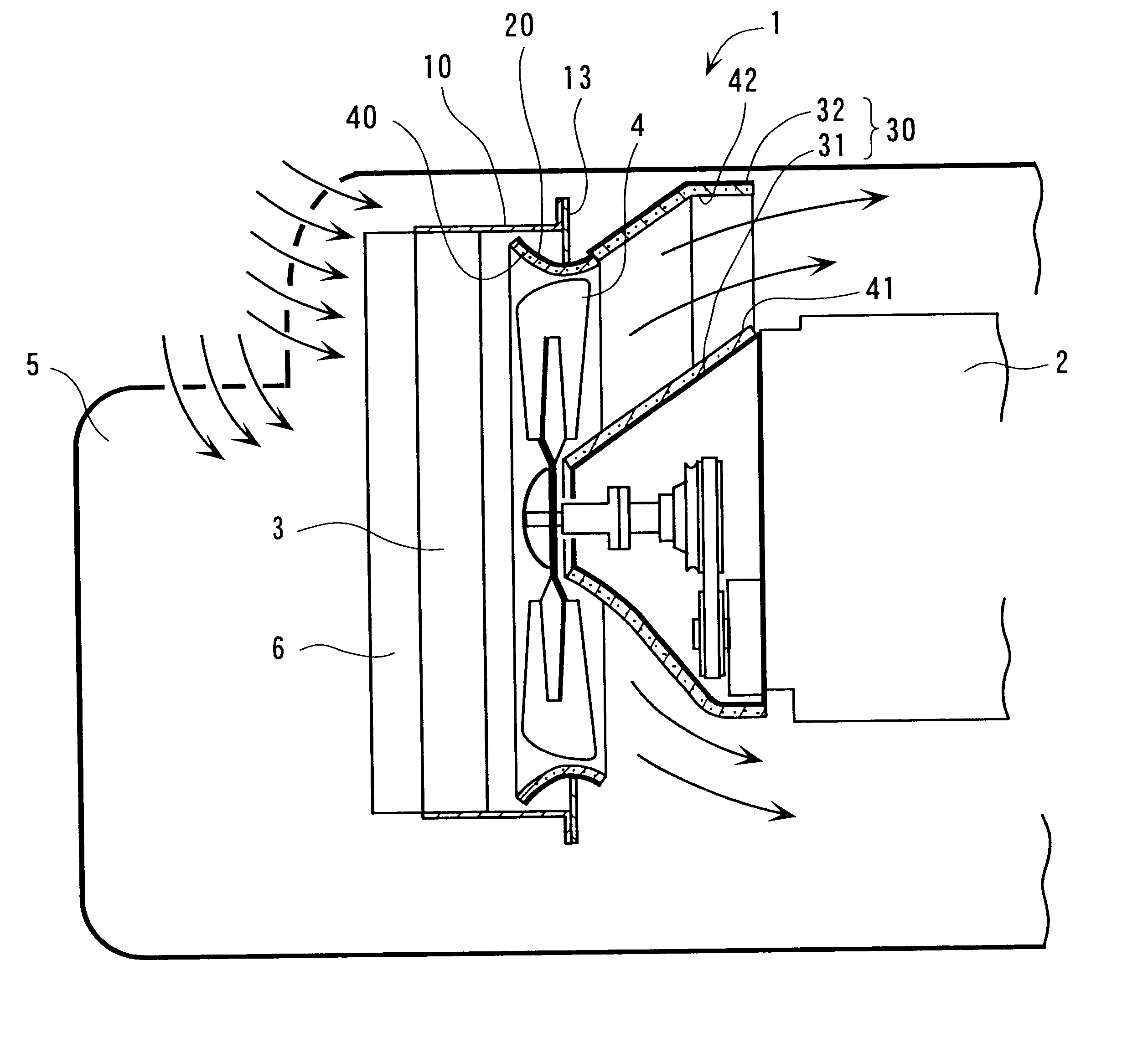
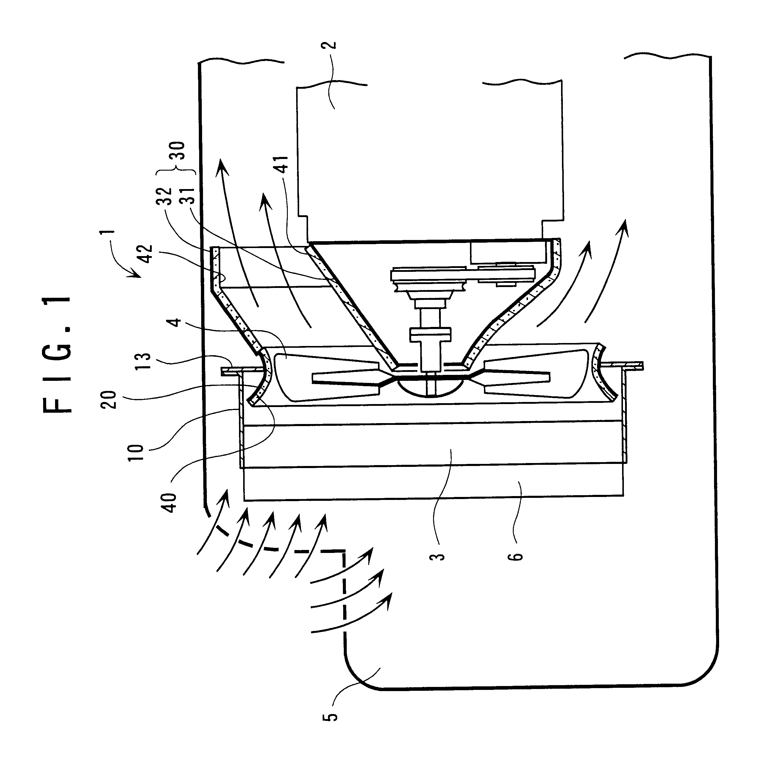
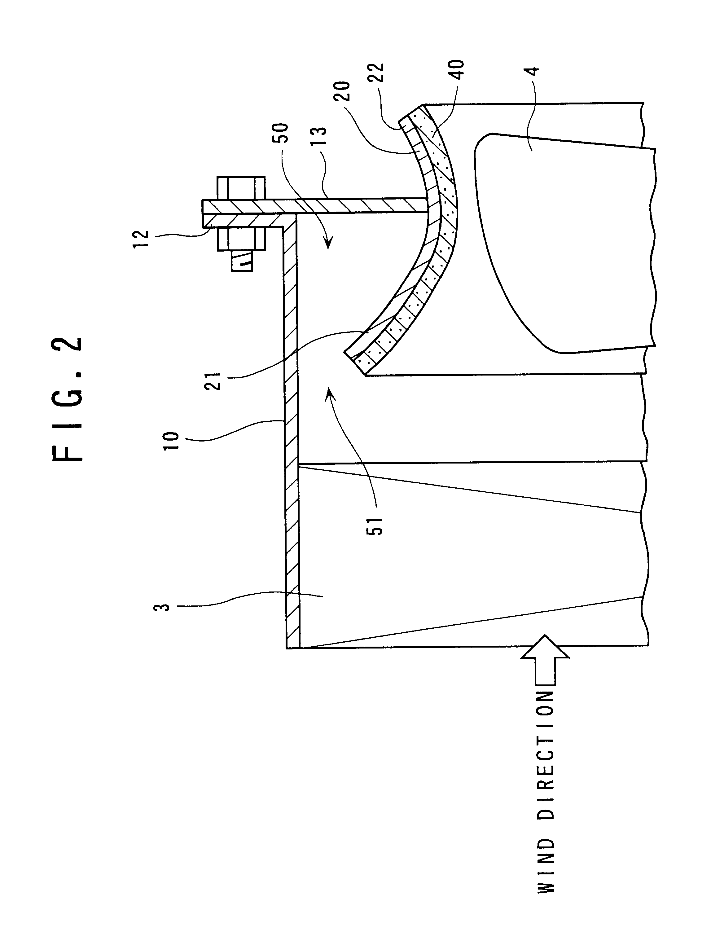
FIG. 1 is an entire view schematically showing the noise reduction system of fan device according to the first embodiment applied to an engine cooling system 1 of construction equipment such as excavator, and FIG. 2 is an enlarged view showing primary portion of the noise reduction mechanism.

The engine cooling system 1 circulates coolant between an engine 2 and a radiator 3 and cools the engine 2 by the coolant whose heat is exchanged by the radiator 3. A fan 4 for sucking in cooling air for heat exchange from the outside is disposed between the engine 2 and the radiator 3, the fan 4 being rotated by power transmitted from a crank shaft of the engine 2 through a pulley and a fan belt.

An oil cooler 6 is disposed on further upstream side (upstream side of the cooling air flow direction) of the radiator 3 (see FIG. 1) and engine oil is circulated between a hydraulic c...

second embodiment

[Second Embodiment]

FIG. 3 schematically shows a primary portion of the noise reduction mechanism of fan device according to second embodiment of the present invention.

The present embodiment differs from the first embodiment in that a number of holes 23 is drilled to the fan shroud 20 and that the upstream opening 21 of the fan shroud 20 is brought further proximal to the inside of the radiator hood 10 to improve degree of enclosure of the damping chamber 50.

According to the present embodiment, following effects can be obtained as well as the effects 1) to 8) of the first embodiment.

9) Since the number of holes 23 is drilled to the fan shroud 20, low-frequency noise of the noise generated during rotation of the fan 4 that easily transmits through the damping material 40 can be reduced by the upstream opening 21. This is because the low-frequency noise can be effectively damped by the holes 23 and the damping chamber 50 in communication with the holes 23 when the low-frequency noise r...

third embodiment

[Third Embodiment]

FIG. 4 shows the third embodiment of the present invention, where damping material 43 is attached to the whole inner circumference of the radiator hood 10 in addition to the arrangement of the second embodiment.

According to the present embodiment, following effect as well as the above effects 1) to 9) can be obtained.

10) The noise can be damped at a larger area on the upstream side of the fan 4 by the damping material 43 attached to the inside of the radiator hood 10, thus enhancing damping effect.


PUM

PropertyMeasurementUnit
noiseaaaaaaaaaa
dampingaaaaaaaaaa
circumferenceaaaaaaaaaa

Abstract

Porous damping material (40) is attached to an entire inner circumference of the fan shroud (20) opposing to an end of a fan (4) and is exposed to opposing space without using conventional perforated metal. Accordingly, jet noise caused by strong swirl between the fan (4) and the fan shroud (20) can be damped by the damping material (40) and impulsive sound scarcely occurs. Thus, both of the impulsive sound and the jet noise can be effectively damped, thereby securely reducing noise. The pours member (401) constituting the porous damping material (40) is a die-molding product made by a die (150) having a cavity (153).

Description

1. Field of the InventionThe present invention relates to a noise reduction mechanism of a fan device and a molding method of porous damping material used therefor. More specifically, it relates to a noise reduction mechanism of a fan device used for engine cooling system of special-purpose vehicle including construction equipment such as excavator and other vehicles, and industrial cooling system.2. Description of Related ArtConventionally, in an engine cooling system of vehicles, coolant is circulated between the engine and radiator. In such cooling system, a fan is attached proximal to the radiator, so that heat is exchanged between cooling air sucked in by the fan and the coolant in the radiator to cool the engine by the coolant after heat exchange.In the above, a fan shroud is provided around the fan to straighten flow of the cooling air passing through the radiator, thus enhancing heat exchange by the radiator to improve cooling efficiency of the engine.A strong swirl is gener...

Claims


Application Information

Patent Timeline
Patent Type & Authority Patents(United States)
IPC IPC(8): F01P11/12F01P11/00F02B77/11F02B77/13F04D29/66F04D29/54F04D29/40F01P5/06F01P11/10F01P5/02
CPCF01P11/12F02B77/13F04D29/545F04D29/664F01P5/06F01P11/10B60K11/06B60K11/08F04D29/526
Inventor NISHIYAMA, TOSHIHIKOKOSHIMIZU, KENGOYABE, MITSUO
Owner KOMATSU LTD
Why Eureka
Try Eureka