In a further developed version of the inventive method, the control parameters are determined depending on the amplification or
gain factor of the transmission-ratio valve and the regulation is performed with parameter values that are corrected in the inverse sense of the
gain of the transmission-ratio valve. This is advantageous in a case where a change in the
transfer function of the regulating valve can be described in terms of a change in the amplification of the valve, e.g., if the valve has a markedly lower amplification in the zero-
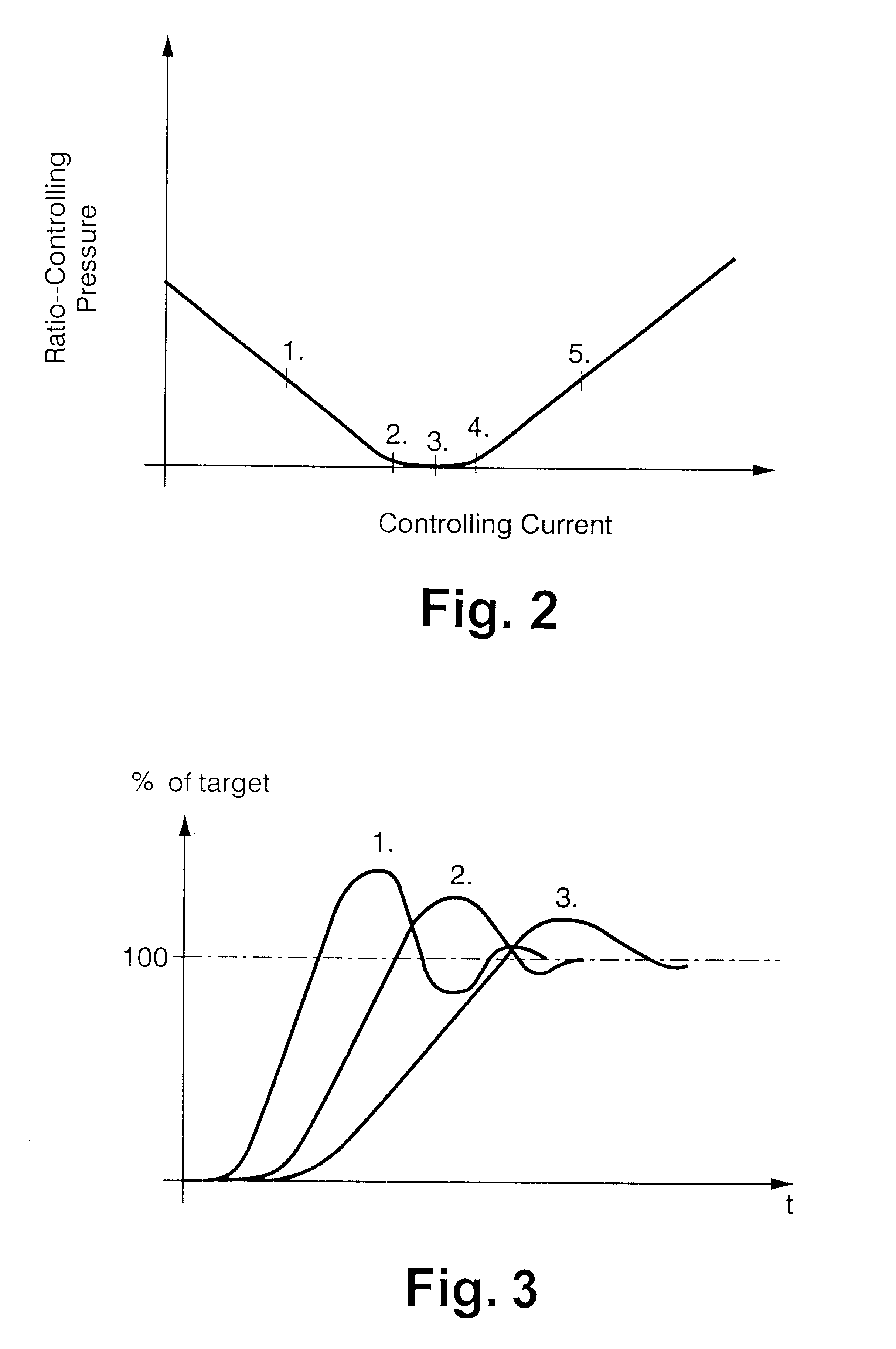
pressure range than in the two ranges adjoining the zero-pressure range. Advantageously, the amplification is expressed in the form of an amplification curve and the correction that is applied to the control parameters is a multiplication by the inverse value of the amplification, so that the non-linear behavior of the ratio-controlling member can thereby be linearized.
The latter concept is advantageous in a case where the
transfer function of the transmission-ratio valve changes as a function of temperature. For example, if the dynamic behavior becomes weaker with increasing temperature, it is advantageous to determine the control parameters dependent on the temperature or to apply a temperature-dependent correction to the control parameters, so that the control parameter values are lowered when there is a weakening of the dynamic response, whereby the regulating servo circuit can be prevented from becoming unstable as would be the case with control parameters of a fixed, constant value. Further under this concept, it is of
advantage if the control parameters are expressed as a temperature-dependent curve. The parameter values used for the regulation could be standard values that are corrected by a certain percentage in accordance with the temperature-dependent curve so as to avoid the unfavorable regulating conditions that occur with fixed control parameters. The
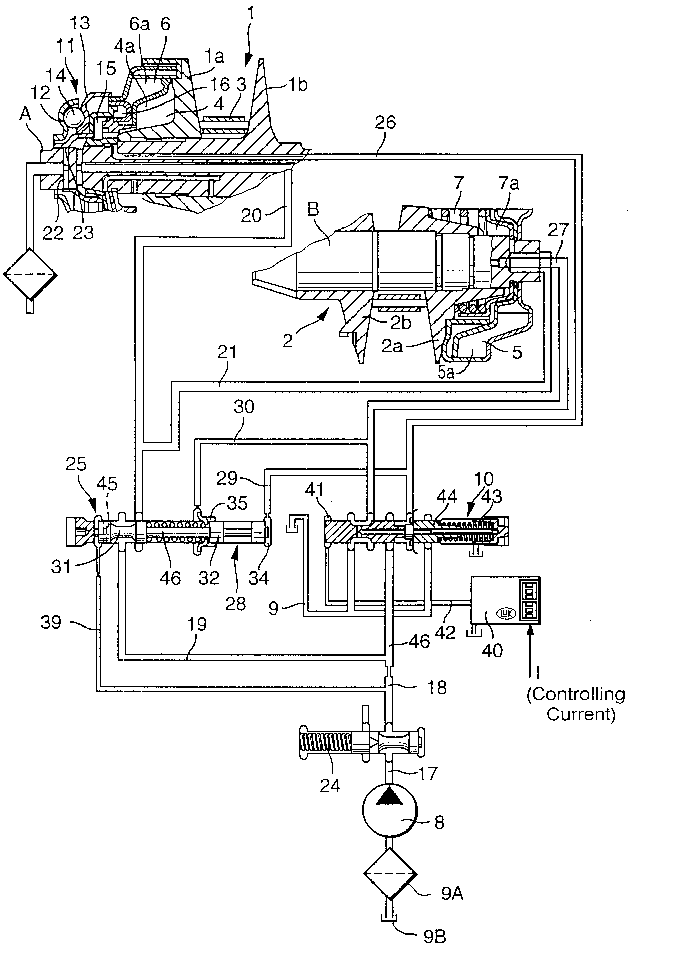
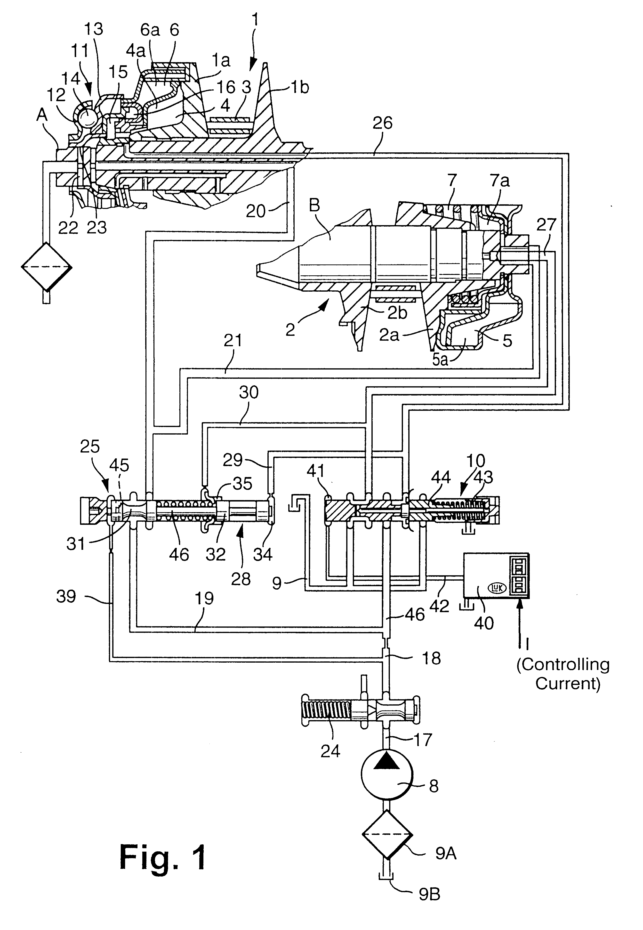
piston / cylinder unit at one disc set or the units at both disc sets are supplied by way of the transmission-ratio valve with a ratio-controlling pressure to set or change the
transmission ratio. The transmission-ratio valve is part of a
hydraulic circuit that is pressurized by a
pump pressure or
system pressure. The transmission-ratio valve receives this
system pressure as input pressure and delivers a ratio-controlling pressure to the
piston / cylinder unit. A further developed embodiment of the invention provides therefore that the control parameters be determined as a function of the ratio between the input pressure and the ratio-controlling pressure. If the regulating behavior of the transmission-ratio valve is changing as a result of a pressure differential between the
system pressure and the ratio-controlling pressure, it is advantageous if this is taken into account in the regulation process and the control parameters used for the regulation are adjusted accordingly. The dynamic behavior of the transmission-ratio valve can become stronger with an increase in the pressure differential, and thus it will be advantageous to apply a corresponding upward correction to the control parameter values in order to shorten the
settling time at the new target pressure.
As has been mentioned above, it is advantageous if the control parameters are expressed in the form of characteristic curves and / or characteristic curve fields and / or equations for the control parameters. According to an embodiment of the invention, a finite number of control parameter values are stored as table values which are used to interpolate intermediate values. This has the
advantage that changes of the control parameters occur as continuous variations rather than in steps, so that there are no discontinuous changes that could adversely affect the comfort level of a vehicle equipped with a cone-pulley transmission that operates according to the present invention.
Until now, the procedure for holding the transmission ratio constant in the reverse
travel mode has been to use a high level of current to generate a high level of
pilot pressure. This leads to a
high ratio-controlling pressure in the piston / cylinder unit that controls the transmission ratio, so that the transmission is held in the slow range or underdrive with a strong
actuator force. As there are unavoidable random variations in the serial production from one transmission unit to the next in regard to the amount of force that each transmission requires for being held safely in the underdrive mode, the use of a high level of current assures that any one of the different transmissions of a series can be held safely in underdrive when driving backwards.
It should be obvious that the
high current level is disadvantageous to the overall fuel consumption of the vehicle and that the high level of ratio-controlling pressure or ratio-controlling force causes a high level of
contact force between the conical discs and the chain-belt, which can cause increased wear on the chain-belt.
To meet this objective, the invention provides a way of setting the transmission ratio of a continuously variable cone-pulley transmission at an essentially constant level. Under the inventive method, the transmission is first set to the targeted ratio by pressurizing at least one piston / cylinder unit, whereupon the same or another piston / cylinder unit is pressurized with a holding pressure for the purpose of maintaining the set transmission ratio. According to the inventive method, the amount of holding pressure is specific to a given transmission, i.e., the holding pressure or holding force, or a current level by which the holding pressure is generated, can be different from one unit to the next, but the amount of holding pressure is selected to be only as large as required in a given individual transmission for maintaining the set transmission ratio. The use of an unnecessarily
high ratio-controlling pressure is thereby avoided.

