Coherent laser radar system and target measurement method

a laser radar and laser radar technology, applied in the direction of distance measurement, instruments, using reradiation, etc., can solve the problems of difficult to reduce the cost and size of the system, the structure of the pulse doppler radar system becomes complicated, and the difficulty of the system to measure the clear air turbulen

Inactive Publication Date: 2002-10-22
MITSUBISHI ELECTRIC CORP
View PDF36 Cites 34 Cited by
  • Summary
  • Abstract
  • Description
  • Claims
  • Application Information

AI Technical Summary

Problems solved by technology

Accordingly, it is difficult for the pulse Doppler radar system to measure the clear-air turbulence because not enough echo is captured in clear weather in which there are no raindrops, particles of mist or cloud in the atmosphere.
In addition, since the CW laser must oscillate the single frequency CW laser beam at a high frequency stability, it becomes complicated in its structure.
As a result, the configuration of the system becomes complex, which presents a problem of making it difficult to reduce the cost and size of the system and to increase its reliability.

Method used


Image

  • Coherent laser radar system and target measurement method
  • Coherent laser radar system and target measurement method
  • Coherent laser radar system and target measurement method

Examples


embodiment 1

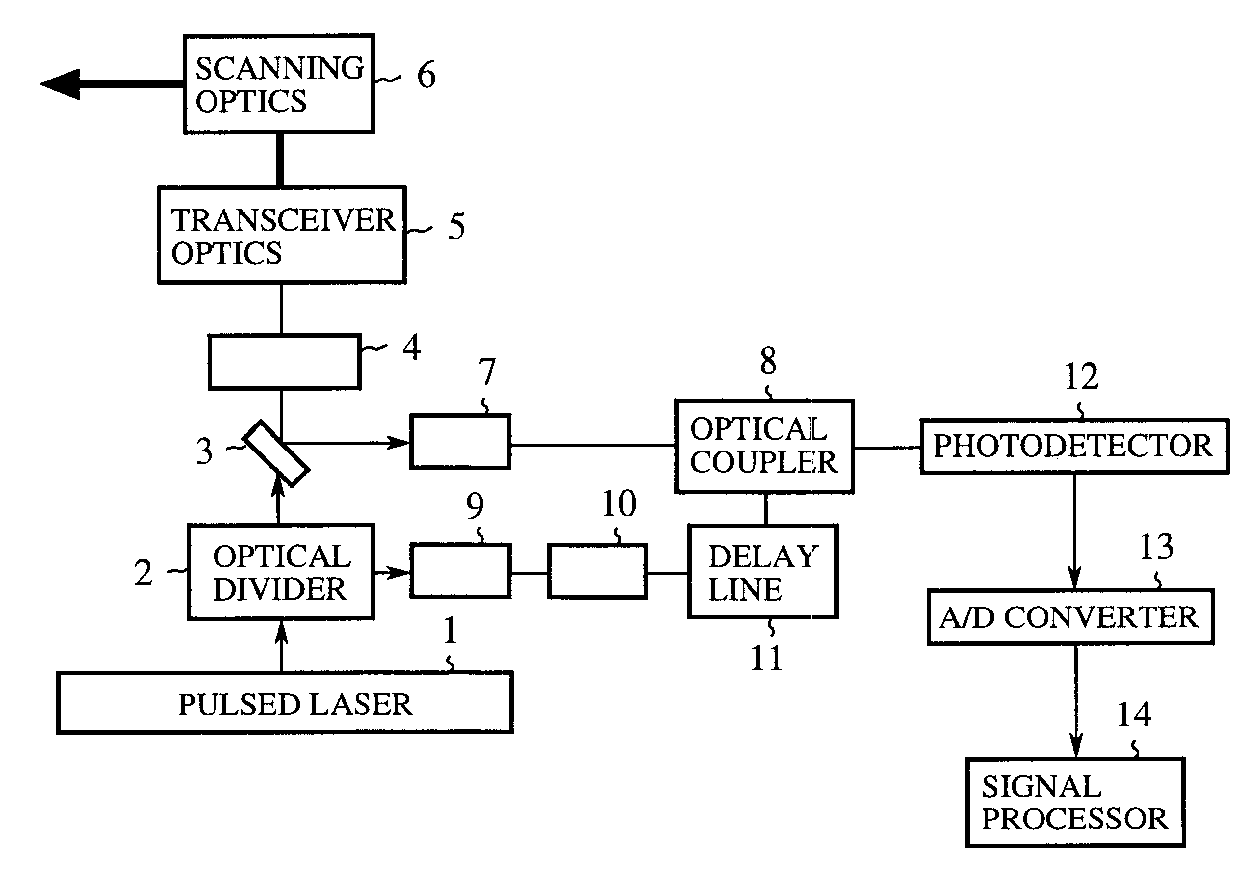
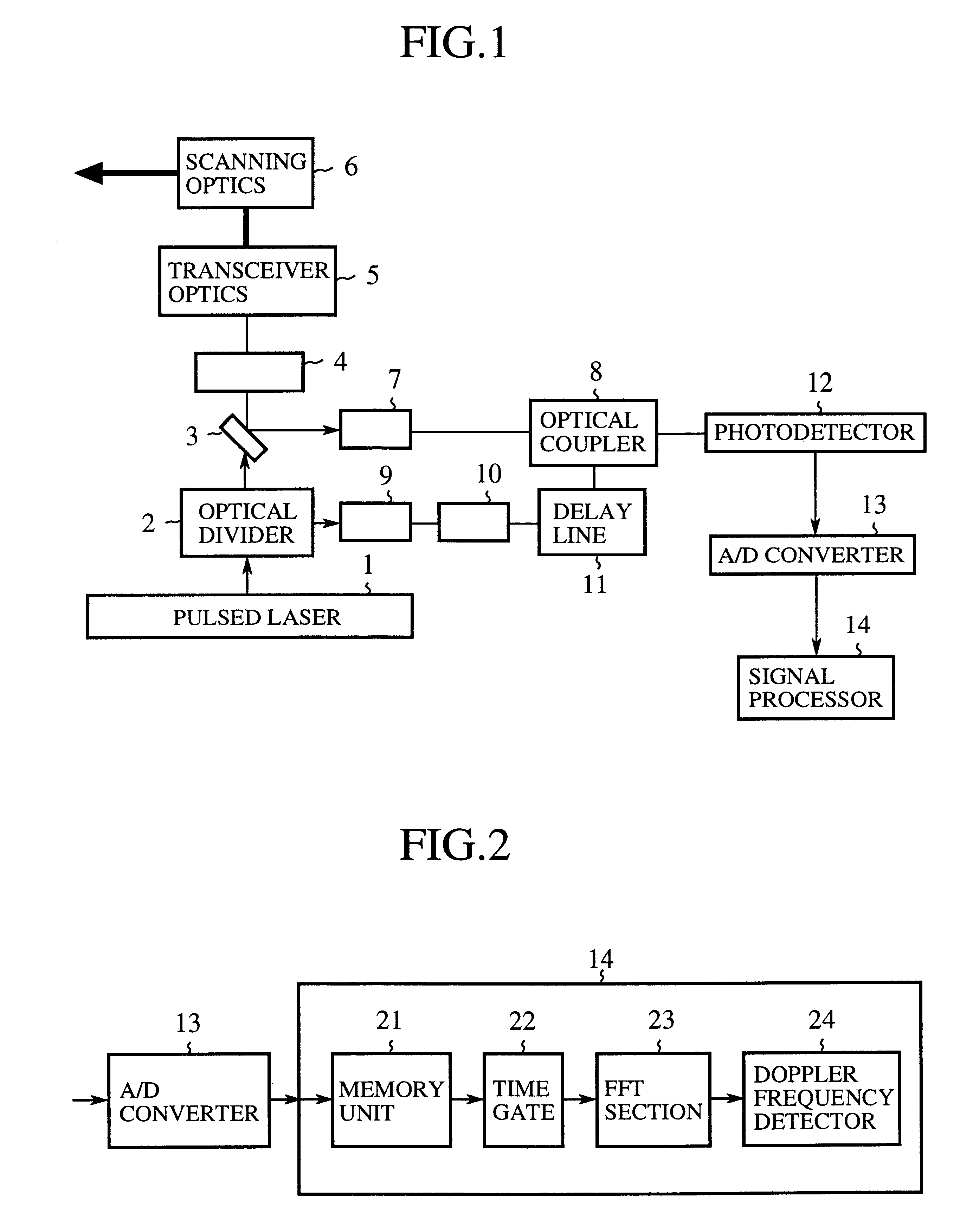
FIG. 1 is a block diagram showing a configuration of the coherent laser radar system in accordance with the present invention. In this figure, the reference numeral 1 designates a pulsed laser for oscillating a single frequency (single wavelength) pulsed laser beam; 2 designates an optical divider for dividing the pulsed laser beam; 3 designates a beam splitter for separating the optical path of a transmitted beam from that of a received beam using the difference in the polarization direction; 4 designates a quarter-wave plate for converting a linearly polarized beam with a predetermined polarization direction with respect to the crystallographic axis into a circularly polarized beam, and for converting a circularly polarized beam into a linearly polarized beam; 5 designates a transceiver optics for supplying the light beam from the quarter-wave plate 4 to a scanning optics 6, and the light beam from the scanning optics 6 to the quarter-wave plate 4 along the same optical path; and ...

embodiment 2

FIG. 5 is a block diagram showing a configuration of the delay line of an embodiment 2 of the coherent laser radar system in accordance with the present invention. The delay line 11 as shown in FIG. 5 comprises an optical divider 31 for splitting the incident local beam to n light beams, where n is greater than one; n delay lines 32-1-32-n for providing the n light beams with different delay times; and an optical coupler 33 for coupling the n light beams passing through the n delay lines.

Since the remaining configuration of the present embodiment 2 of the coherent laser radar system is the same as that of the embodiment 1 (FIG. 1), the description thereof is omitted here.

Next, the operation of the present embodiment 2 will be described.

FIG. 6 is a timing chart illustrating the operation of the present embodiment 2 of the coherent laser radar system, in which case, the target is assumed to be a soft target like atmosphere.

In the delay line 11 of the embodiment 2, the optical divider ...

embodiment 3

FIG. 7 is a block diagram showing a configuration of the delay line of an embodiment 3 of the coherent laser radar system in accordance with the present invention. The delay line 11 as shown in FIG. 7 comprises a loop line 41 for transmitting laser beam; and an optical coupler 42 for guiding an incident local beam into the loop line 41, and for dividing part of the light beam passing through the loop line 41.

Since the remaining configuration of the present embodiment 3 of the coherent laser radar system is the same as that of the embodiment 1 (see, FIG. 1), the description thereof is omitted here.

Next, the operation of the present embodiment 3 will be described.

FIG. 8 is a timing chart illustrating the operation of the embodiment 3 of the coherent laser radar system. The target in this case is assumed to be a soft target like atmosphere.

The optical coupler 42 guides the pulsed laser beam (single pulse) from the frequency shifter 10 to the ring-like loop line 41, so that the introduc...


PUM

PropertyMeasurementUnit
physicalaaaaaaaaaa
velocityaaaaaaaaaa
density distributionaaaaaaaaaa

Abstract

A coherent laser radar system includes a pulsed laser oscillating a pulsed laser beam which is split into two parts by an optical divider. A first part of the two is transmitted as a transmitted beam via a beam splitter. A second part is supplied to a delay line via a coupling optics and others to be delayed by a predetermined time as a local beam, and is incident onto an optical coupler. The received beam from the target is incident onto the optical coupler via a scanning optics and so on. A photodetector carries out the coherent detection of the light beam coupled by the optical coupler. A signal processor computes a target velocity and the like from a signal generated by the detection and converted into a digital signal by an A / D converter. This makes it possible to solve a problem of a conventional system in that the system configuration is complicated and expensive.

Description

1. Field of the InventionThe present invention relates to a coherent laser radar system and a target measurement method for measuring physical information such as a target distance, velocity, density distribution and velocity distribution of the target, and particularly to a coherent laser radar system and a target measurement method utilizing a pulsed laser oscillating a single-wavelength (single-frequency) pulsed laser beam as a light source.2. Description of Related ArtAs devices for measuring physical information such as the target distance, velocity, density distribution and velocity distribution of the target, there are a pulse Doppler radar system utilizing microwaves or millimeter waves and a coherent laser radar system utilizing light waves (laser beam). Because of the difference between their frequencies, the former can perform wide-range, long-distance measurements, whereas the latter can perform measurements at high spatial resolution and high velocity resolution.In soft...

Claims


Application Information

Patent Timeline
Patent Type & Authority Patents(United States)
IPC IPC(8): G01S17/10G01S17/00G01S7/48G01S7/486G01S7/481H01S3/00G01S17/42G02F1/33H01S3/10
CPCG01S7/4818G01S7/486G01S17/10
Inventor ASAKA, KIMIOHIRANO, YOSHIHITOYANAGISAWA, TAKAYUKIWADAKA, SHUSOUOOGA, YASUISASUGIMOTO, ETSUO
Owner MITSUBISHI ELECTRIC CORP
Why Eureka
Try Eureka