Focusing systems for perspective dimensional measurements and optical metrology

a technology of optical metrology and focusing system, which is applied in the field of optical metrology, can solve the problems of loss of calibration, no inherent ability of the user to quantitatively measure the size of the objects he or she is viewing, and new optical calibration

Inactive Publication Date: 2002-11-05
SCHAACK DAVID F
View PDF9 Cites 31 Cited by
  • Summary
  • Abstract
  • Description
  • Claims
  • Application Information

AI Technical Summary

Problems solved by technology

While endoscopes (both flexible and rigid) can give the user a relatively clear view of an inaccessible region, there is no inherent ability for the user to make a quantitative measurement of the size of the objects he or she is viewing.
Making a truly accurate measurement under these circumstances is a long-standing problem that has not been adequately solved until recently.
The problem is that a new optical calibration may have to be performed each time the focus of the instrument is adjusted.
When a standard borescope is used with my previous invention, there is the further difficulty that when an image sensor is mounted to the borescope to perform perspective measurements and the assembly is then calibrated, this calibration is lost if the image sensor is subsequently removed from the borescope.
The fundamental problem with this approach to making accurate dimensional measurements is that the position at which the image is in focus is difficult to determine, thus the range measurement, and hence the magnification, is subject to relatively large random errors (that is, a lack of repeatability).
As a result, these instruments, as disclosed and in practice, are restricted to making two dimensional measurements, i.e., measurements of distances that are oriented perpendicular to the optical axis.
This assumption cannot apply to any three-dimensional measurement technique because the measurement determines the depth of an object, while only a single plane of the object can truly be in focus at a time.
These techniques have the same problem as does the measurement by focus technique when it comes to accurate metrology.
While the system taught by Watanabe and Nayar meets the goals they set for it, their teachings are far from complete.
In addition, their teachings are in error in an important point, in that they state that their system will also work if the lens is moved with respect to the image viewing plane.
The problem addressed by Quinn was that objects near the edge of the field of view of a vide...

Method used


Image

  • Focusing systems for perspective dimensional measurements and optical metrology
  • Focusing systems for perspective dimensional measurements and optical metrology
  • Focusing systems for perspective dimensional measurements and optical metrology

Examples


first embodiment

The layout of the optical system of this first embodiment is depicted in FIG. 11. A lens surface, 125, represents the most proximal surface of the eyepiece lens of the borescope. Then, successively to the right along optical axis 8 are depicted borescope exit pupil 22, projection lens 788 with front and rear principal planes PP1 and PP2, and the image sensing surface of focal plane array 770. Also indicated are extreme axial positions 770a and 770b that the sensing surface of array 770 may take due to the action of translation slide 780 (FIGS. 8 and 9). The range of motion includes a position slightly inside of the rear focal point of lens 788.

Exit pupil 22 lies approximately 12 to 20 mm behind lens surface 125, depending on the optical and mechanical design of the borescope being used. When the system is aligned as discussed below, projection lens 788 is mounted so that its front focal point lies in the plane of exit pupil 22, as shown in FIG. 11.

3. Operation of the First Embodimen...

second embodiment

where FD is the distance between the position of sensor 770 and its position when an object at infinity is in focus, z is the in-focus position of the object along the optical axis, z.sub.EntP is the position of the entrance pupil of the borescope along the optical axis, f.sub.p is the focal length of the projection lens, and M.sub.B is the paraxial angular magnification of the borescope. The entrance pupil is simply the image of the aperture stop of the borescope as viewed from the object side of the scope. The paraxial angular magnification of the borescope and the other quantities used in Equation (10) will be explained in more detail in the discussion of the operation of the

Image sensor 770 is also provided with the capability to move closer to lens 788 than one focal length of that lens in case the borescope happens to be focused on objects somewhat closer than infinity. This enables the system as a whole to be focused on objects at infinity even when the borescope itself is no...

third embodiment

9. Description of a Third Embodiment

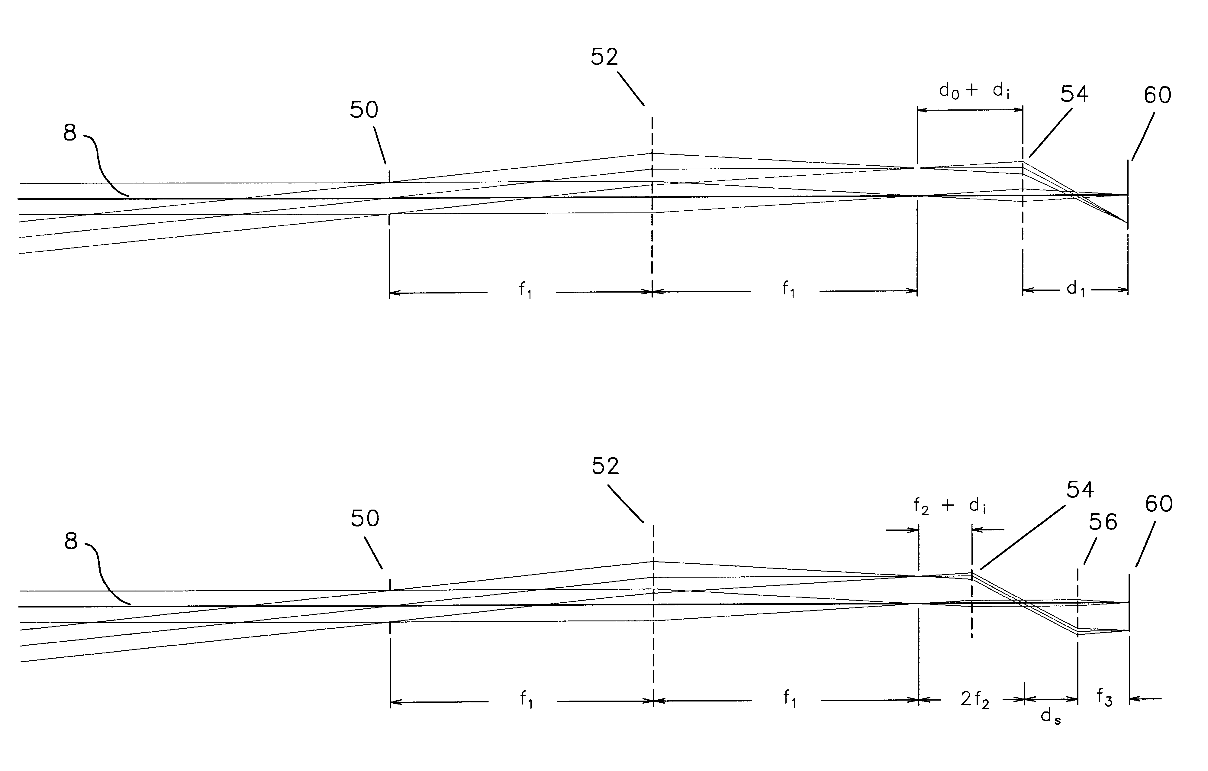
The optical system of a third embodiment of a measurement camera for use with a borescope is depicted in FIG. 31. The left hand side of this Figure is the same as FIG. 11, because the optical system is a modification of that of the first embodiment. As in the first embodiment, a most proximal lens vertex 125 of a borescope is shown, as is also a borescope exit pupil 22. A projection lens 788 is located centered on optical axis 8 at a distance of one focal length away from exit pupil 22, just as in the first embodiment.

At the right hand side of FIG. 31 is a generic image sensing plane 60. The sensing plane is denoted by a different number than it was in either of the first two embodiments to indicate the fact that with this third system, no particular sort of image sensing plane is preferred.

Located between projection lens 788 and image sensing plane 60 is an afocal focusing lens group 920 that consists of a first focusing lens 922 and a second foc...


PUM


Abstract

Focusing systems for which variation of magnification with focus is either inherently compensated, or is calibrated and corrected. The required conditions for inherent compensation are determined, and the desired state is called constant relative magnification. It is shown that telecentricity does not guarantee constant relative magnification. Both telecentric and non-telecentric accessory cameras for endoscopes are disclosed that have constant relative magnification, as are additional optical systems for general metrological purposes. Methods for calibrating change in relative magnification and deviation of the optical axis with focal shift are disclosed, as are methods for incorporating these changes into perspective dimensional measurements. Embodiments are disclosed in which only a single quantity need be measured to perform the correction, and these embodiments require only a low-resolution position transducer to provide accurate measurements. Apparatus is disclosed that enables an accessory camera to be aligned to an endoscope using only externally accessible adjustments. This apparatus also makes it possible to de-mount the camera from one endoscope and re-mount it to another without requiring any recalibration.

Description

STATEMENT REGARDING FEDERALLY SPONSORED RESEARCH AND DEVELOPMENT(Not Applicable)1. Field of the InventionThis invention relates to optical metrology, and particularly to the problem of making accurate non-contact dimensional measurements of objects that are viewed through an endoscope.2. Description of Related Art2a. Perspective Dimensional Measurements with EndoscopesIn the past several decades, the use of optical endoscopes has become common for the visual inspection of inaccessible objects, such as the internal organs of the human body or the internal parts of machinery. These visual inspections are performed in order to assess the need for surgery or equipment tear down and repair; thus the results of the inspections are accorded a great deal of importance. Accordingly, there has been much effort to improve the art in the field of endoscopes.Endoscopes are long and narrow optical systems, typically circular in cross-section, which can be inserted through a small opening in an en...

Claims


Application Information

Patent Timeline
IPC IPC(8): G02B23/24G02B7/04
CPCG02B7/04G02B23/2407
Inventor SCHAACK, DAVID F.
Owner SCHAACK DAVID F
Why Eureka
Try Eureka