
Car body energy absorber and bumper stay

a technology for car body and energy absorption, applied in the field of energy absorption, can solve the problems of less collision energy absorption, increased weight, and insufficient bending strength of the body

Inactive Publication Date: 2002-11-19
KOBE STEEL LTD
View PDF27 Cites 70 Cited by
  • Summary
  • Abstract
  • Description
  • Claims
  • Application Information

AI Technical Summary

Benefits of technology

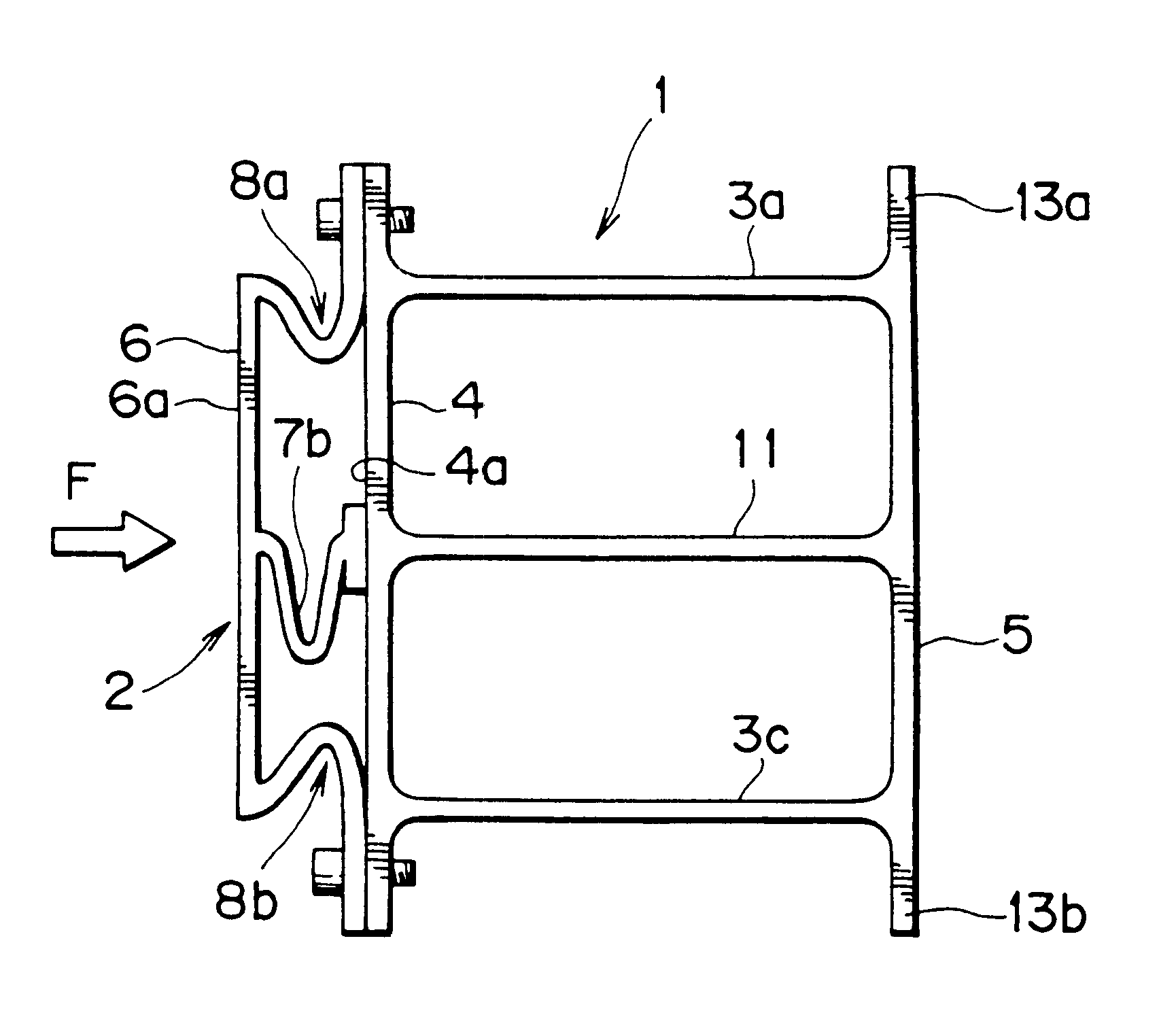
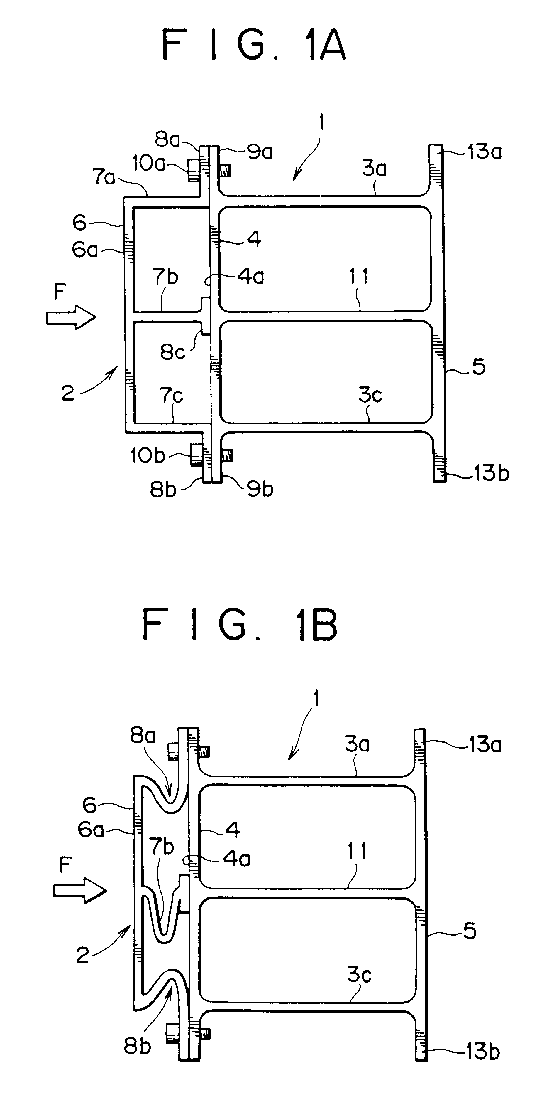
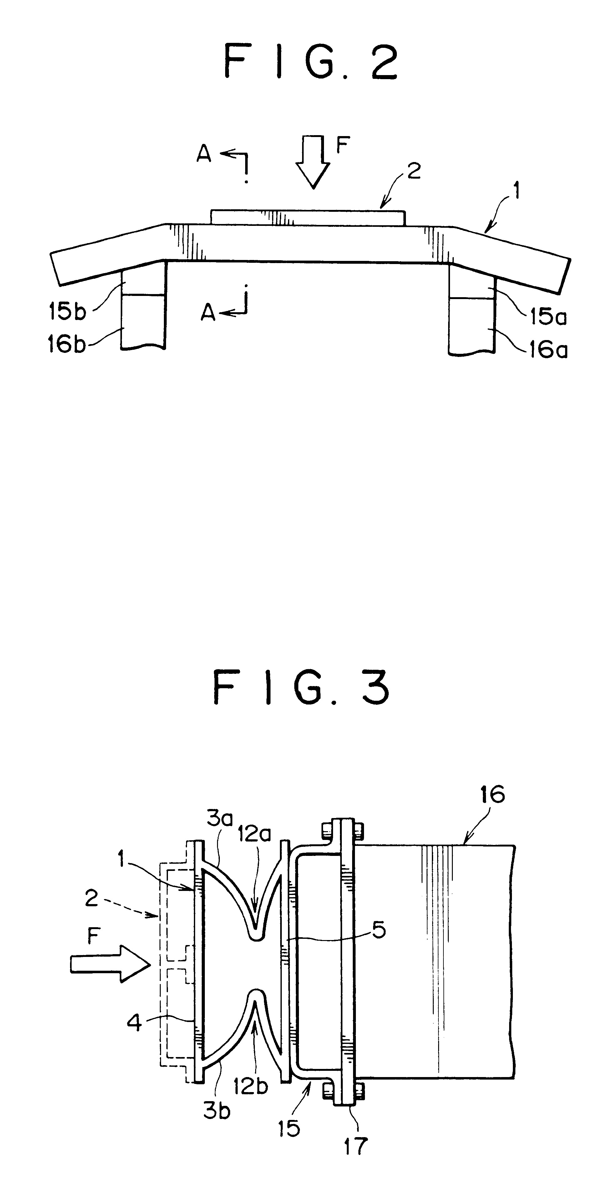
The car body energy absorber according to this invention offers the following advantages. Firstly, since the hollow shape and the reinforcing shape are aluminum alloy extruded shapes, the overall weight of the absorber is smaller and the weight increase due to the addition of the reinforcing shape is also relatively small. Secondly, what is particularly important is that, since the reinforcing shape has not a hollow, closed rectangular sectional profile having four sides but an open sectional profile and, it is possible to increase the strength while maintaining the weight increase due to the addition of the reinforcing shape at the minimum level. Thirdly, it is easy to attach because the reinforcing shape is connected with the hollow shape's collision plane through the vertical flanges located at the tips of the horizontal ribs.
The stay according to this invention is made of an Al alloy which is chosen from among AA or JIS 5000, 6000 and 7000 series Al alloys. These Al alloys are suitable for the stay according to this invention because they are excellent in formability, have a high strength and can thus be easily manufactured by extrusion or a similar technique.

Problems solved by technology

However, a body energy absorber which consists of an Al alloy extruded hollow shape with a virtually rectangular sectional profile has the following problem: if it is used for rear bumper reinforcement, its bending strength may be insufficient with respect to the virtually horizontal force (of vehicle collision) applied to the body energy absorber when the body collides against a pole.
However, if the strength of the Al alloy shape is increased, it might be more difficult to make shapes by extrusion or bending and such shapes might be more likely to crack, resulting in less collision energy absorption.
Also, an increase in the thickness of the Al alloy shape or the width of the bumper reinforcement will lead to an increase in weight, which means that the lightness of Al alloy is traded off for increased strength.
If the thickness of the Al alloy shape should be simply increased, the maximum load (force) of a collapsing bumper reinforcement might be larger than the permissible maximum load for side members, and it would be very likely to damage body members such as front side members.
Yet still, because the weight of the hollow shape reinforcement with a closed sectional profile is added, the problem of weight increase remains in comparison with the case of absence of an auxiliary reinforcement.
However, the auxiliary reinforcement has a hollow structure with a closed sectional profile and uses inner ribs (props) to reinforce it, so the collapse strength of the auxiliary reinforcement is rather high.
Therefore, if the wall thickness of the bumper reinforcement main body is decreased as stated above, upon collision against a pole or in a similar situation, the bumper reinforcement main body might collapse earlier than the auxiliary reinforcement.
Further, because the auxiliary reinforcement is a hollow shape with a closed sectional profile, it is virtually impossible to join it to the bumper reinforcement main body mechanically or using bolts or the like or by welding.
Consequently, the fixing method which uses glue as described in the gazette is unavoidable.
However, gluing is much more unreliable as a method for fixing a vehicle structural member than a mechanical fixing method or welding.
Even when the contact surfaces of both are matched, there still remains another problem: how they should be joined and fixed.
However, these conventional joining / fixing methods have drawbacks.
First of all, they are impractical and sometimes even ineffective.
In the above-said conventional methods, it is practically difficult to put a bolt into the inside of the bumper reinforcement and stay which are both hollow and have a closed sectional profile.
It is even more difficult for a bumper reinforcement with a curved portion at each end.
It is also practically difficult to let the bolt's top and bottom stay in the hollows with the bolt passed through them as suggested by the conventional methods.
Further, it is unrealistic to join and fix the stay to the front of the side member according to the prior art for the following reasons.
One reason is that it is difficult to position the above-said hollow attachment on the side member in the car body widthwise direction.
Besides, even if the hollow attachment is once positioned on and engaged with the side member, it is difficult to let the bolt's top or bottom stay in the hollow of the side member or stay attachment with the bolt passed through them horizontally from the side of the car body.
Firstly, since the hollow shape and the reinforcing shape are aluminum alloy extruded shapes, the overall weight of the absorber is smaller and the weight increase due to the addition of the reinforcing shape is also relatively small.
However, if the stay has a hollow, closed sectional profile, it would be difficult to attach it to the side member.
However, this method makes attachment of the reinforcing shape 2 to it and its attachment to the car body as mentioned later complicated.
Thus, in order to join them by a simpler method, it would be necessary to rely on glue as in the method (described earlier) disclosed by J-P-A-No. 286536 / 1994, which would make the connection less reliable.

Method used


Image

  • Car body energy absorber and bumper stay
  • Car body energy absorber and bumper stay
  • Car body energy absorber and bumper stay

Examples


Embodiment Construction

1

Next, embodiments of the present invention will be described. A car body rear bumper reinforcement that has a structure as shown in FIG. 1 is assumed as an embodiment sample 1. To realize it, a hollow shape 1 with a rectangular sectional profile and a reinforcing shape 2, both as made of T5-treated JIS 6NO1 Al alloy (proof stress 240N / mm.sup.2) by extrusion, were prepared.

T5-treated JIS 6NO1 Al alloy is widely used as a material for absorbing car body energies and, if a collision force is applied, is more likely to crack than JIS 7000 series Al alloys such as JIS 7003 Al alloy. Therefore, if the extruded shapes made of JIS 6NO1 Al alloy prove effective as intended by this embodiment, the result may be reflected in extruded shapes made of 7000 series Al alloy such as 7003 Al alloy.

For the purpose of comparison, sample 2, which consists of only a hollow shape 1 or does not comprise a reinforcing shape 2, was prepared. Also, a bumper reinforcement, which consists of an extruded shape ...


PUM

PropertyMeasurementUnit
lengthaaaaaaaaaa
thicknessaaaaaaaaaa
lengthaaaaaaaaaa

Abstract

A lightweight car body energy absorber made of Al alloy which provides a high energy absorption performance. The car body energy absorber comprises a hollow shape with a rectangular sectional profile and a reinforcing shape attached to the front face of the collision plane of the hollow shape, where the hollow shape and the reinforcing shape are aluminum alloy extruded shapes. The reinforcing shape has a hat-shaped open sectional profile, which is composed of a collision wall almost parallel to the collision plane of the hollow shape, plural mutually parallel horizontal ribs which support the collision wall, and vertical flanges provided at the tips of these ribs. The reinforcing shape is joined to the collision plane of the hollow shape through the vertical flanges.

Description

1. Field of the InventionThis invention relates to energy absorbers as extruded shapes made of aluminum alloy which have a high strength to resist a car body's collision against a pole (aluminum is hereinafter called Al). It is also concerned with bumper stays to be attached to the body side face of the curved end portions of a bumper reinforcement having curved portions at both ends.2. Description of Related ArtA car body incorporates body energy absorbers such as bumper reinforcements and door beams. The bumper fitted to the front or rear of the body has, in its inside, a bumper reinforcing member called a bumper reinforcement or bumper reinforce.Recently, for the sake of lightness, there has been an increasing tendency to use extruded shapes of high-strength aluminum alloys (which have the same sectional profile in the longitudinal direction) such as JIS 5000, 6000 and 7000 series instead of steel shapes which were often used formerly.Al alloys are higher in such energy absorptio...

Claims


Application Information

Patent Timeline
Patent Type & Authority Patents(United States)
IPC IPC(8): B60R19/24B60R19/18B60R19/02B60R19/04
CPCB60R19/18B60R19/24B60R2019/182B60R2019/186B60R19/02B60R19/04
Inventor KARIATSUMARI, KOJINIMURA, SATOSHIHASHIMURA, TORU
Owner KOBE STEEL LTD
Learn More