Ink jet recording head and recording apparatus having recording element substrates with different liquid ejection systems

a recording element and liquid ejection technology, applied in printing and other directions, can solve the problems of increasing the number of times liquid must be ejected, increasing the number of times of liquid ejection, and new problems in the overall performance of the printer

Inactive Publication Date: 2002-11-19
CANON KK
View PDF12 Cites 11 Cited by
  • Summary
  • Abstract
  • Description
  • Claims
  • Application Information

AI Technical Summary

Benefits of technology

It is preferable that a density of arrangement of said recording elements in said recording element substrates to which the chromatic liquid is supplied is approx. Two times the density of arrangement of said recording elements in said recording elements substrates to which the blackish liquid is supplied. By doing so, the recording elements for the black color and the recording elements for the chromatic color can be actuated at the same frequencies, and therefore, the high-speed printing is accomplished with a simple structure and without degrading the durability.
With such a structure, it is possible that the black droplet may be large so that solid black can be printed at a high speed, while the chromatic color droplet may be small so that high-resolution color printing is accomplished.
With the structure, after the color recording liquid is ejected out, the bubble pressure escapes to the outside, and therefore, the vibration of the meniscus is small, so that high speed liquid refilling is accomplished.

Problems solved by technology

If a solid image is printed by ejecting microscopic liquid droplets, the number of times liquid must be ejected becomes rather large, and therefore, recording time tends to become longer.
These methods, however, have created new problems in terms of the overall performance of a printer.
That is, the application of a design for forming a microscopic liquid droplet to the aforementioned black, cyan, magenta, and yellow ink ejecting portions which employ the aforementioned BTJ method, results in variance in ejection velocity and liquid droplet volume, tending to make the color ink ejecting portions about the same as, or inferior to, the black ink ejecting portion, in terms of the accuracy with which an ink droplet lands on a predetermined point on recording medium.
However, this makes it impossible to increase the driving frequency, and therefore, increases the amount of mist created during liquid ejection.
However, as the frequency at which the heaters are driven per unit of time when these liquid ejecting portions are in a printer has been gradually increased, the number of the heaters which can be employed has reached a limit, making it impossible to provide a high density recording head which can be efficiently driven.
In addition, from the standpoint of realizing an ejection velocity higher than a predetermined level, and also the standpoint of stabilizing liquid droplet size, it has become evident that it is very difficult to realize a printer in which both the black ink ejecting portion and color ink ejecting portions perform at their satisfactory performance levels.
Such a design, however, makes a printer extremely expensive and large, which is not practical.

Method used


Image

  • Ink jet recording head and recording apparatus having recording element substrates with different liquid ejection systems
  • Ink jet recording head and recording apparatus having recording element substrates with different liquid ejection systems
  • Ink jet recording head and recording apparatus having recording element substrates with different liquid ejection systems

Examples


embodiment 1

Next, referring to FIGS. 5-12, the first embodiment of the present invention will be described.

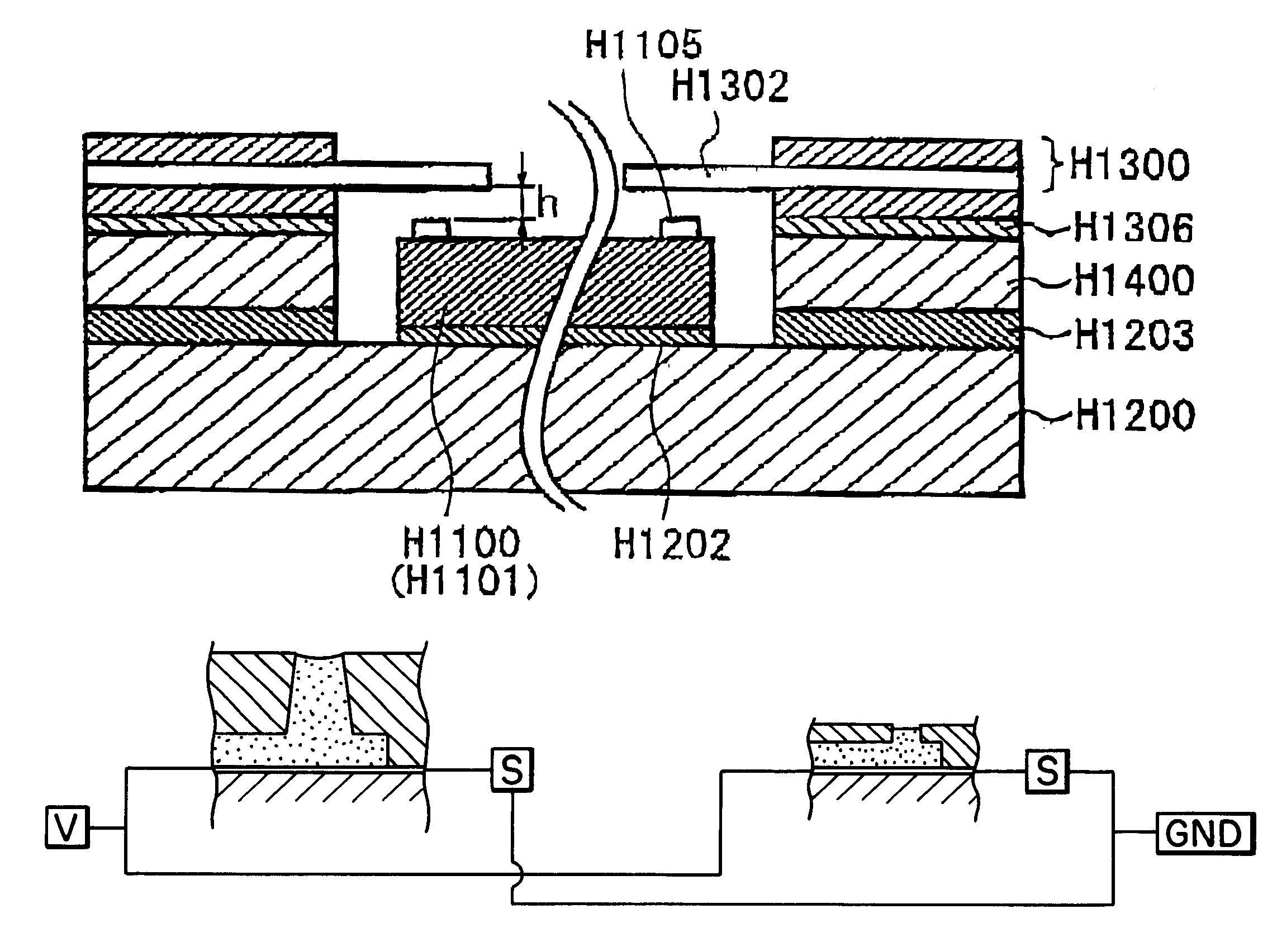
FIG. 5 is a rough, exploded, and sectional view of the essential portion of the recording element unit H1002, and FIG. 6 is a rough sectional view of the essential portion of the recording element unit H1002.

As is evident from FIG. 5, the fringe portions, or bonding portions, of the electric wiring tape H1300 has three layers, which are a base film H1300a of polyimede, or the surface layer; a copper foil H1300b, or the middle layer; and a solder resist H1300c, or the bottom layer. This electric wiring tape H1300 is provided with the device holes (opening) H1 and H2 in which the first and second recording element chips H1100 and H1101 are fitted, respectively. It is also provided with inner leads H1302 (electrode leads) to be connected the bumps H1005 of the recording element chips H1100 and H1101. The inner leads H1302 are plated with gold and are exposed from the electric wiring tape H130...

embodiment 2

This second embodiment will be described about only the portions different from those in the first embodiment, with reference to FIGS. 17-18.

FIG. 17 shows a modified version of the recording element chip in the first embodiment, wherein FIG. 17(a) is a front view and FIG. 17(b) is a sectional view. FIG. 18 is a perspective view of an ink jet recording head in which the recording element chips shown in FIG. 17 have been mounted.

Referring to FIG. 17(c), the second recording element chip 800, or the recording element chip for color recording, in this embodiment comprise a substrate 67 inclusive of a plurality of electrothermal transducers 65 (recording elements) as energy transducing elements, and an orifice plate 66 which contains a plurality of ejection orifices 61. The substrate 67 is formed of a single crystal of silicon with a plane orientation of . Disposed on the substrate 67 are: a plurality of columns of electrothermal transducers 65; a plurality of driving circuits 63 for dri...


PUM


Abstract

An ink jet recording head includes a plurality of recording element substrates each having a plurality of recording elements for applying ejection energy to recording liquid; a plurality of flow paths for the recording liquid which is to receive ejection energy; a supply port for supplying the recording liquid to the plurality of flow paths; a plurality of ejection outlets for ejecting the recording liquid, the ejection outlets being disposed face to the recording elements, respectively; wherein distances between the recording elements and the ejection outlets in at least one of the recording element substrates are different from distances between the recording elements and ejection outlets of another one of the recording element substrates, and wherein liquid ejection systems of the recording elements of the at least one of the recording element substrates and the recording elements of the another one of the recording element substrates, are different.

Description

FIELD OF THE INVENTION AND RELATED ARTThe present invention relate to a recording apparatus which records an image by ejecting recording liquid such as ink, in the form of a droplet, from its ejection orifices. It also relates to an ink jet recording head used for such a recording apparatus. Not only can an ink jet recording head in accordance with the present invention be usable with an ordinary printing apparatus, but also with such an apparatus as a copying machine, a a facsimile machine equipped with a communication system, or a word processor equipped with a printing portion, or an industrial recording apparatus intricately combined with various processing apparatuses. An ink jet recording apparatus is a recording apparatus based on a so-called nonimpact recording method. It is characterized that it is capable of recording on various recording media at a high speed, and makes virtually no noises while recording. Thus, an ink jet recording apparatus is widely used as an apparatu...

Claims


Application Information

Patent Timeline
Patent Type & Authority Patents(United States)
IPC IPC(8): B41J2/14B41J2/16B41J2/21
CPCB41J2/14024B41J2/1601B41J2/1623B41J2/1628B41J2/1631B41J2/1632B41J2/1634B41J2/1635B41J2/1637B41J2/1643B41J2/1645B41J2/2103B41J2002/14475B41J2002/14169
Inventor KANEKO, MINEOTSUCHII, KENTSUKUDA, KEIICHIRO
Owner CANON KK
Why Eureka
Try Eureka