Differential pressure transducer

a technology of pressure transducer and differential pressure, which is applied in the direction of fluid pressure measurement by electric/magnetic elements, measurement devices, instruments, etc., can solve the problems of no longer a linear relationship between, development of relatively expensive and complex pressure transducers, and inability to ensure the long-term serviceability of pressure transducers

Inactive Publication Date: 2002-11-26
BOURDON HAENNI HLDG
View PDF10 Cites 27 Cited by
  • Summary
  • Abstract
  • Description
  • Claims
  • Application Information

AI Technical Summary

Benefits of technology

The differential pressure transducers known to date are not suited for production with methods of planar technology. They have components with structures which are essentially three-dimensional and their production is structurally complex. In the pressure transducer as claimed in DE-A1-31 06 835 this applies especially to the compensation device which comprises an electromagnet with a coil and a permanent magnetic armature, and the two have structurally complex three-dimensional structures. Conversely, the microengineering (and thus flat) coil of the differential pressure transducer according to the invention can be produced with means and methods of microengineering. In this way the possibility of economical, large-series production of the differential pressure transducer as claimed in the invention is established. At the same time, the microengineering structure of the coil yields an outstanding possibility for miniaturization not only of the coil itself, but the entire differential pressure transducer in accordance with the invention. By miniaturizing the pressure transducer the measurement errors which are caused by gravity can be greatly reduced, since the weight of the membrane decreases with the cube of the geometric dimensions. The reduction of the influence of gravity then allows the use of mechanically softer materials for producing the measurement membrane. In this way the choice of materials which can be used to produce the measurement membrane is greatly increased so that some chemically resistant materials can be used which, to date, had not been considered for the measurement membrane of known pressure transducers, because their low mechanical strength under the influence of gravity and / or large differential pressures has / have caused overly large measurement errors.
In the differential pressure transducer as claimed in the invention, the feedback principle is used to measure the differential pressure. The pressure difference to be measured between the two measurement spaces is applied to the membrane device. By means of the differential pressure either directly (i.e. without pressure transfer) or indirectly (i.e. after amplifying or weakening the pressure) a deflection force is produced which causes deflection of the measurement membrane of the membrane device from its neutral position. A deflection sensor measures the deflection of the measurement membrane from its neutral position, produces a deflection signal which corresponds to this deflection, and supplies it to an electrical switching device. The measurement membrane is coupled by magnetic means and an electromagnetic arrangement which comprises a current-conducting coil to the housing of the pressure transducer, i.e there is a magnetic force which is acting directly or indirectly between the measurement membrane and the housing. The switching device is electrically connected to the coil of the electromagnet arrangement and produces a coil current such that the coil interacts by means of magnetic force with the magnetic means such that overall a force is exerted by the housing on the measurement membrane which essentially compensates for the deflection force acting on the measurement membrane in order to cancel the deflection of the measurement membrane from its neutral position. This is, in turn, measured by the deflection sensor (thus the feedback loop is closed). As a measure for the differential pressure the strength of the coil current which is necessary to produce the magnetic compensation force is measured. This in contrast, for example, to the differential pressure transducers of the type described in WO 96 / 41141 where the deflection of the measurement membrane is used as a measure for the differential pressure. Thus, in the differential pressure transducer according to the invention, large deflections of the measurement membrane are avoided. This yields the advantage that, in the pressure transducer of the invention, the measurement membrane need not meet high demands with respect to its mechanical properties in terms of to elasticity and / or linearity. In particular, it is feasible to produce the measurement membrane of the invention using those materials which are mechanically soft and / or which have a small linear elasticity range but, for example, are especially resistant to corrosion.
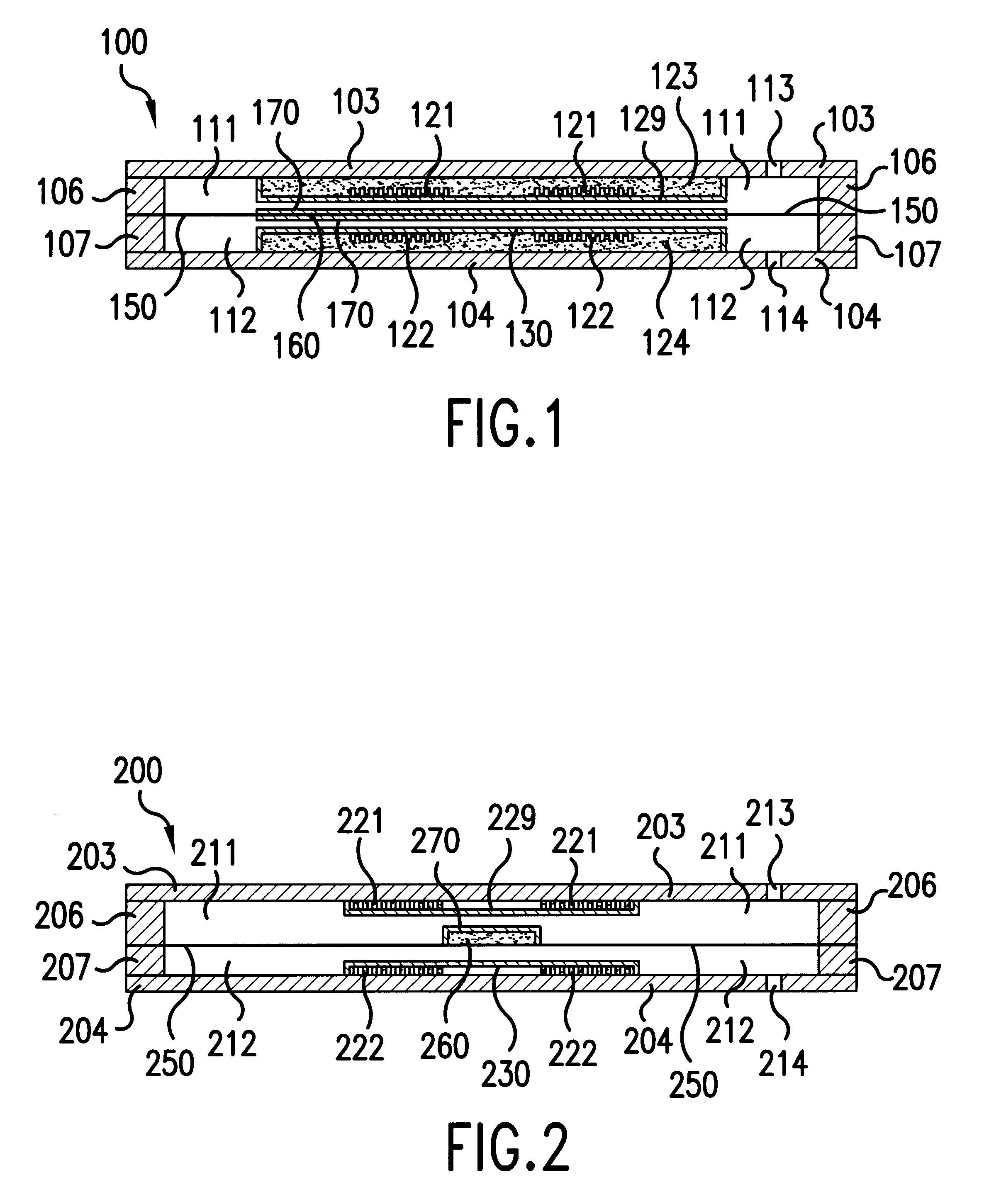
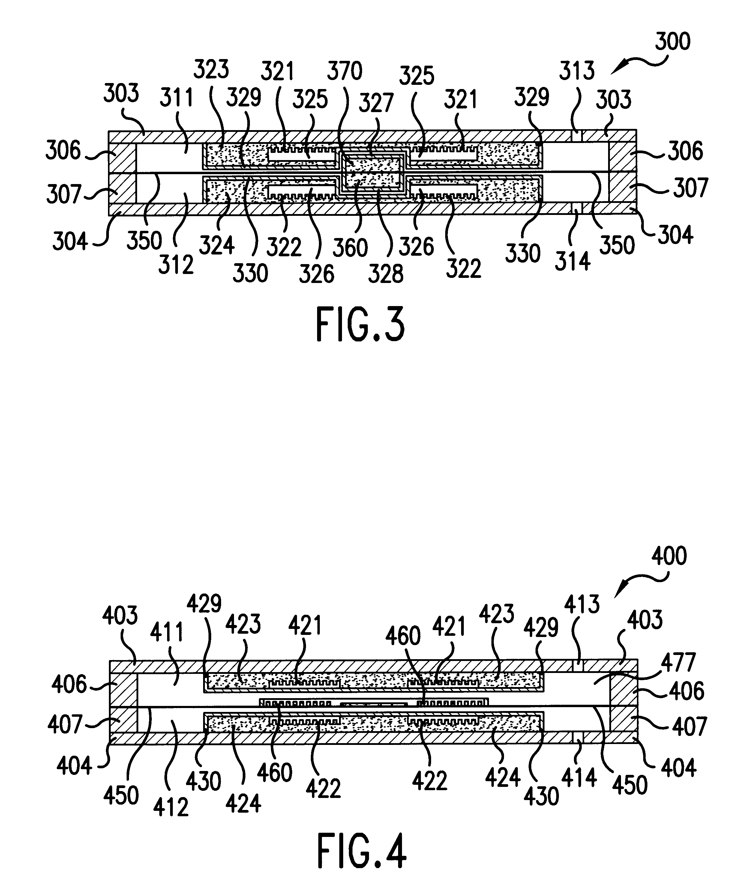
Advantageously the measurement membrane is located in the measurement chamber which is defined by the housing such that the housing walls ensure effective overload protection against mechanical overloads of the measurement membrane. This is done by the distance which is perpendicular to the plane of the measurement membrane between the measurement membrane and the housing walls which border the measurement chamber being chosen to be as small ask possible. When the measurement membrane is overloaded as a result of the overly large differential pressure then the measurement membrane contacts one housing wall and is supported by it, thus preventing inelastic extension of the measurement membrane.
Advantageously the electromagnet arrangement is made and arranged essentially symmetrical with respect to a plane of symmetry which is defined by the measurement membrane, in order to reduce the formation of the asymmetrical temperature distributions which cause errors in pressure measurement. These asymmetrical temperature distributions are often the cause of errors in pressure measurement by means of differential pressure transducers. With the symmetrical formation of the electromagnet arrangement at the same time position-dependent errors can be actively compensated, which even in the pressure transducer as claimed in the invention are still present as a result of the action of gravity on the measurement membrane when the latter is not positioned vertically.
According to one preferred embodiment of the invention the membrane device comprises simply a single membrane in the form of the measurement membrane, the membrane device being made and the measurement membrane being arranged such that one side of the measurement membrane is directly exposed to the first measurement pressure and the other side of the measurement membrane is directly exposed to the second measurement pressure. This embodiment of the invention enables simple construction of the membrane device with simply one single membrane.
The measurement membrane however can also be produced from a conventional membrane material and / or by means of suitable treatment of the surface it can be protected against corrosion and / or other chemical reactions.

Problems solved by technology

The necessity of precise measurement of small differential pressures, typically roughly 100 mbar, around a high absolute (conventionally static) pressure of for example 100 bar, has led to development of relatively expensive and complex pressure transducers, since these devices on the one hand must demonstrate their serviceability in the transfer from ambient pressure to high absolute operating pressure and on the other hand must be sensitive enough to be able to measure small differential pressures with the desired accuracy.
In pressure transducers of this type the problem is that, as a result of the elasticity of the measurement membrane, which is linear only in a narrow range, for larger deflections of the measurement membrane there is no longer a linear relationship between the change of the differential pressure and the corresponding change of inductance.
Furthermore, there is the danger of inelastic deformations of the membrane which adulterate the measurement results over the long term, for which reason the long term serviceability of the pressure transducer is not ensured.
In addition, temperature changes and / or corrosion can significantly change the material properties of the membrane; this can lead to further measurement errors.
However, the differential pressure measurement means as claimed in DE-A1-31 06 835, as also otherwise all other known pressure transducers, has a complicated and expensive structure; this makes it unsuited for economical production in large series.
At the same time the force of gravity in all known pressure transducers with a measurement membrane represents another error source in that under the influence of gravity the measurement membrane can already be deformed as a result of its inherent weight; this results in an error in pressure measurement which is dependent on the position of the pressure transducer.

Method used


Image

  • Differential pressure transducer
  • Differential pressure transducer
  • Differential pressure transducer

Examples


Embodiment Construction

The object of this invention is to make available a differential pressure transducer which is structurally simple, which can be economically produced in large series, and which is long-lived and itself enables reliable differential pressure measurements under ambient conditions which are severe with respect to corrosion and temperature.

The differential pressure transducer according to the invention has a measurement chamber which is defined by a housing and which is divided by a membrane device into a first measurement space which can be exposed to a first measurement pressure and a second measurement space which can be exposed to a second measurement pressure. The membrane device comprises at least one measurement membrane, the membrane device being arranged and made such that a deflection force which is engendered by the first measurement pressure and the second measurement pressure causes deflection of the measurement membrane from its neutral position. The pressure transducer fu...


PUM

PropertyMeasurementUnit
pressureaaaaaaaaaa
diameteraaaaaaaaaa
diameteraaaaaaaaaa

Abstract

A differential pressure transducer has a measurement chamber which is divided by a membrane into first and second measurement spaces which can be exposed to first and second pressures whereby differential pressure causes deflection of the membrane from its neutral position. A deflection sensor measures the deflection of the membrane and produces a deflection signal. An electromagnet arrangement produces a magnetic force which compensates for the deflection force which is caused by the differential pressure. The coil current for producing the magnetic compensation force represents a measure of the differential pressure.

Description

This invention relates to an differential pressure transducer which is especially suited for measuring the differential pressure in a severe industrial environment.PRIOR ARTA differential pressure transducer is defined as a measurement means for measurement of differential pressure.Differential pressure transducers are widely used for example in the chemical industry, food industry, aviation industry, in water treatment plants, etc. for purposes of among others flow measurement in flowing media, the control of filters, speed measurement in aircraft or water craft. The necessity of precise measurement of small differential pressures, typically roughly 100 mbar, around a high absolute (conventionally static) pressure of for example 100 bar, has led to development of relatively expensive and complex pressure transducers, since these devices on the one hand must demonstrate their serviceability in the transfer from ambient pressure to high absolute operating pressure and on the other ha...

Claims


Application Information

Patent Timeline
Patent Type & Authority Patents(United States)
IPC IPC(8): G01L9/00G01L13/06
CPCG01L9/007
Inventor DUTOIT, BERTRANDFRIEDRICH, ANDREASHUG, KURTPOPOVIC, RADIVOJC
Owner BOURDON HAENNI HLDG
Why Eureka
Try Eureka