Ink-jet head base board, ink-jet head, and ink-jet apparatus

a technology of inkjet head and inkjet head, which is applied in the field of inkjet head base board, inkjet head and inkjet apparatus, which can solve the problems of chemically affecting the ink itself, the proportion and the intense heat of the inkjet head

Inactive Publication Date: 2002-11-26
CANON KK
View PDF11 Cites 21 Cited by
  • Summary
  • Abstract
  • Description
  • Claims
  • Application Information

AI Technical Summary

Problems solved by technology

When ink is ejected, the portion of the ink-jet head, which thermally interacts with ink, is subjected to not only the intense heat generated by the exothermic resistant material, but also the shocks (cavitation shocks) caused by the formation and collapsing of ink bubbles.
Also, it is chemically affected by the ink itself.
After reaching its peak, it began to fall due to heat dissipation.
This is due to the fact that the thicker the protective layer, the longer the time necessary for the damage or corrosion to reach the exothermic resistant layer, and therefore, the longer the service life of the head.
When such improved ink, in particular, ink which contains ingredients, such as Ca and Mg, capable of forming bivalent metallic salt, or chelate complex, is used, the protective layer tends to be corroded through a thermochemical reaction which occurs between the protective layer and ink.
However, increasing the thickness of the protective layer results in the reduction in the efficiency with which the thermal energy generated in the exothermic resistant layer conducts to the thermally interactive surface.
Howeve

Method used


Image

  • Ink-jet head base board, ink-jet head, and ink-jet apparatus
  • Ink-jet head base board, ink-jet head, and ink-jet apparatus
  • Ink-jet head base board, ink-jet head, and ink-jet apparatus

Examples


example 1

Film Formation Example 1

In the following tests, an amorphous alloy film layer equivalent to the top portion protecting layer was formed on a piece of silicon wafer using the apparatus illustrated in FIG. 4, along with the above described film forming method. Then, the properties of the formed amorphous alloy film were evaluated. The description of the film forming operation, and the results of the evaluation of the formed amorphous alloy film will be given below.

Film Forming Operation

First, the surface of a single crystal silicon wafer is thermally oxidized, and this silicon wafer (substrate 4004) was placed on the substrate holder 4003 in the film formation chamber 4009 of the apparatus illustrated in FIG. 4. Next, the interior of the film formation chamber 4009 was evacuated to a level of 8.times.10.sup.-6 Pa by a vacuum pump 4007. Thereafter, argon gas was introduced into the film formation chamber 4009 through the gas introduction opening 4010, and the ambience condition within ...

embodiment 1

Evaluation of Suitability of Film Samples as Top Portion Protecting Layer of Ink-jet

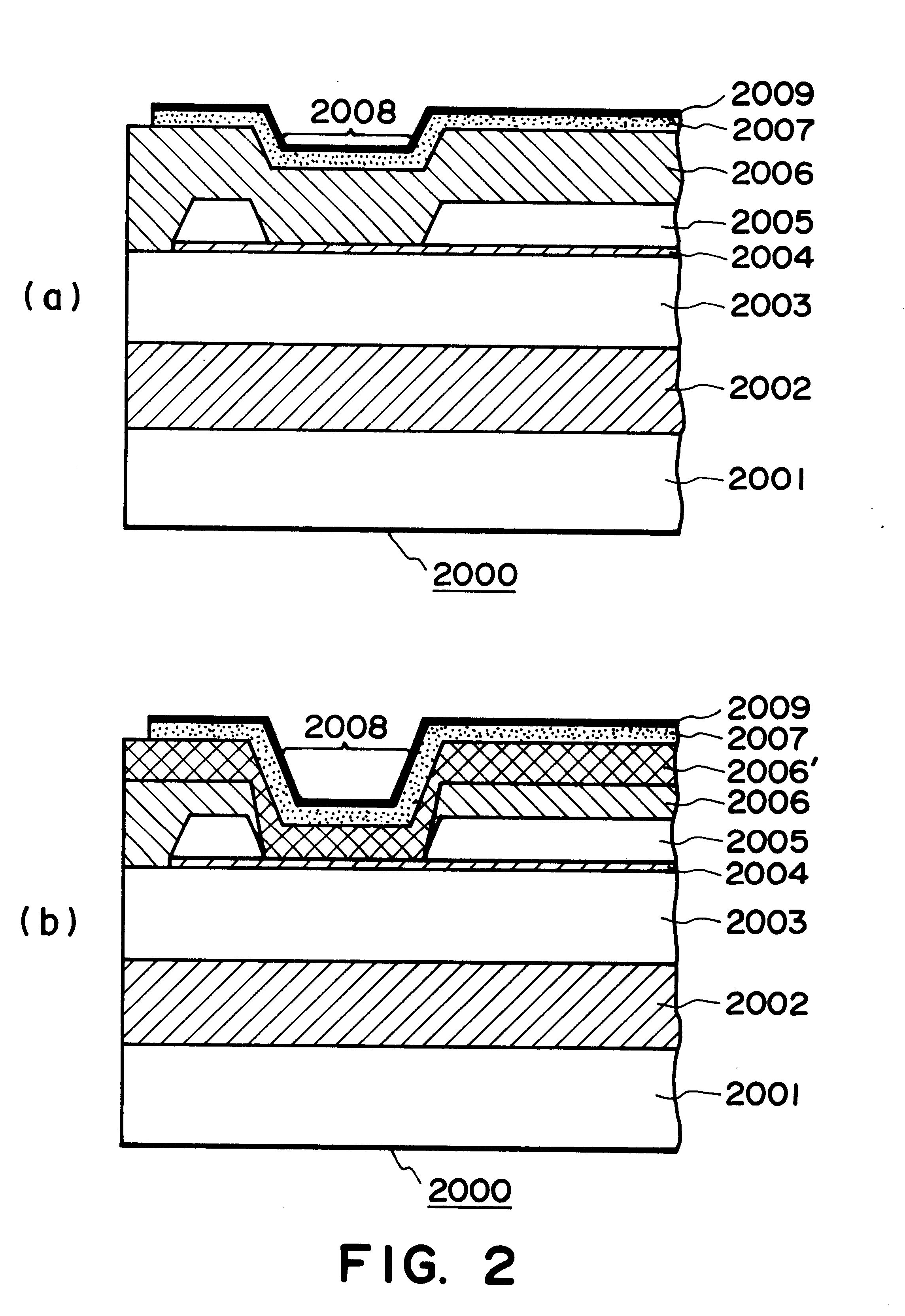
The substrate of the samples evaluated to determine the characteristics of the ink-jet in this embodiment was a piece of plane Si substrate, or a piece of Si substrate on which a driver IC had been already built in. In the case of the plane Si substrate, the heat storage layer 2002 (FIG. 2(b)), that is, a 1.8 .mu.m thick layer of SiO.sub.2, was formed thereon by such a method as thermal oxidization, sputtering, CVD, or the like. In the case of the Si substrate with the IC, the heat storage layer, or the SiO.sub.2 layer, was formed similarly to the case of the Plane Si substrate, during its manufacturing process.

Next, an interlayer insulative film 2003, that is, a 1.2 .mu.m thick film of SiO.sub.2, was formed by sputtering, CVD, or the like methods. Next, the exothermic resistant layer 2004, that is, a 500 nm thick Ta.sub.35 Si.sub.22 N.sub.43 alloy layer, was formed by a method of reactive sputtering...

embodiments 2-5

Ink-jet heads, which were identical to those in the first embodiment except that the top portion protecting layers 2007 were given the compositions and thicknesses shown in Table 2, were produced, and were tested for endurance like those in the first embodiment. The results are given in Table 2.


PUM


Abstract

A base member for an ink jet head, the base member comprising a substrate, a heat generating resistor provided between electrodes which constitute a pair on the substrate an upper protection layer provided on an insulation layer which in turn is provided on the heat generating resistor, the upper protection layer having a contact surface contactable to ink, the improvement residing in thatthe upper protection layer is made of amorphous alloy having a following composition formula:where 10 atomic %<=alpha<=30 atomic %, alpha+beta<80 atomic % alpha<beta, delta>gamma and, alpha+beta+gamma+delta=100 atomic %, and at least the contact surface of the upper protection layer contains an oxide of a constituent component.

Description

FIELD OF THE INVENTION AND RELATED ARTThe present invention relates to a base board for forming an ink-jet head (hereinafter, it may be referred to "head" for simplicity) which prints letters, signs, images, or the like on recording medium such as paper, plastic sheet, fabric, ordinary objects, and the like, by ejecting functional liquid, for example, ink, onto the recording medium. It also relates to an ink-jet head comprising such a base board, a recording unit, for example, an ink-jet pen, comprising an ink storage portion for storing the ink supplied to such an ink-jet head, and an ink-jet apparatus in which such an ink-jet head is installed.There are various configuration for a recording unit, such as an ink-jet pen, in accordance with the present invention. One of such configurations is a cartridge. A cartridge may comprise an integral or independent combination of an ink-jet head and an ink storing portion. An ink-jet recording unit is structured so that it can be removably m...

Claims


Application Information

Patent Timeline
IPC IPC(8): B41J2/14B41J2/16B41J2/05B41J2/235
CPCB41J2/14129B41J2/1604B41J2/1623B41J2/1631B41J2/1642B41J2/1646B41J2/235
Inventor SAITO, ICHIROOGAWA, MASAHIKOOZAKI, TERUOKUBOTA, MASAHIKOMOCHIZUKI, MUGA
Owner CANON KK
Why Eureka
Try Eureka