Halogenated anti-reflective coatings

a technology of anti-reflective coating and halogenated polymer, which is applied in the direction of photosensitive materials, instruments, photomechanical equipment, etc., can solve the problems of reducing the image quality of the processed photoresist, and reducing the resolution of the photoresis

Inactive Publication Date: 2002-12-17
BREWER SCI
View PDF8 Cites 19 Cited by
  • Summary
  • Abstract
  • Description
  • Claims
  • Application Information

AI Technical Summary

Problems solved by technology

However, a frequent problem encountered by photoresists during the manufacturing of semiconductor devices is that activating radiation is reflected back into the photoresist by the substrate on which it is supported.
Such reflectivity tends to cause blurred patterns which degrade the resolution of the photoresist.
Degradation of the image in the processed photoresist is particularly problematic when the substrate is non-planar and / or highly reflective.
While these ARCs are effective at lessening the amount of light reflected back into the photoresist, most prior art ARC compositions are lacking in that they do not have a sufficiently high etch rate.
As a result, prior art ARCs present significant limitations which make them difficult or impossible to use on submicron (e.g., 0.3 .mu.m) features.
This faster etch rate is particularly important because prior art ARCs have etched substantially slower than the photoresist layer, thus resulting in overetching of the remaining photoresist layers.

Method used


Image

  • Halogenated anti-reflective coatings
  • Halogenated anti-reflective coatings
  • Halogenated anti-reflective coatings

Examples


example 2

In this example, copolymers were halogenated on the backbone of the copolymer, and the etch selectivity of the halogenated copolymer was determined as compared to a reference (P-HPMA). The tested copolymers are represented by Formulas II-IV. The etch selectivity results are set forth in Table 2. The etch rate was not improved or only mildly improved when halogens were added directly to the polymer backbone. ##STR4##

Poly-hydroxypropylmethacrylate (P-HPMA) ##STR5## ##STR6## ##STR7##

example 3

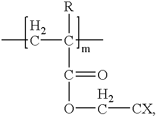
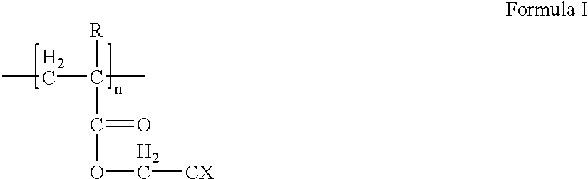
In this example, copolymers were halogenated on functional groups of the copolymer (i.e., the halogens were not attached directly to the polymer backbone) which was grafted with a chromophore. The respective etch selectivities of the resulting ARCs were determined as compared to a reference (DUV42, see Formula V). The tested copolymers are represented by Formula VI. The etch selectivity results are set forth in Table 3. ##STR8## ##STR9##

Where "R" is --H or --CH.sub.3, and "X" is --F.sub.3 or --Cl.sub.3, as indicated in Table 3.
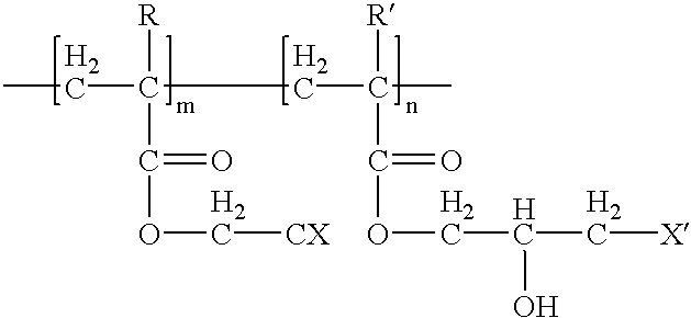
example 4

In this example, copolymers were halogenated on a functional group of the copolymer (i. e., the halogens were not attached directly to the polymer backbone) which was grafted with a chromophore similar to Example 3. The etch selectivity of the ARC was then determined. The copolymers of the polymer binder in the tested ARC are represented by Formula VII, with varying molar ratios of "m" and "n" being tested. The etch selectivity results are set forth in Table 4. These results indicate that ARCs formed with polymers having halogentated functional groups can have the molar ratio of the copolymer members varied to adjust the properties of the ARC. ##STR10##


PUM

PropertyMeasurementUnit
weight average molecular weightaaaaaaaaaa
temperatureaaaaaaaaaa
weight average molecular weightaaaaaaaaaa

Abstract

Anti-reflective coatings formed from new polymers and having high etch rates are provided. Broadly, the coatings are formed from a polymer binder and a light attenuating compound. The polymer binder has halogen atoms bonded thereto, preferably to functional groups on the polymer binder rather than to the polymer backbone. Preferred polymer binders comprise acrylic polymers while it is preferred that the halogenated functional groups of the polymer binders be dihalogenated, and more preferably trihalogenated, with chlorine, fluorine, or bromine atoms.

Description

1. Field of the InventionThe present invention is broadly concerned with new halogenated polymers which can be used as polymer binders in anti-reflective coatings, the resulting anti-reflective coatings, and methods of use thereof. More particularly, the inventive anti-reflective coatings comprise a polymer binder and a light attenuating compound wherein the polymer binder is halogenated, preferably on functional groups of the polymer binder. The coatings have high etch rates as well as good light-absorbing properties.2. Description of the Prior ArtIntegrated circuit manufacturers are consistently seeking to maximize substrate wafer sizes and minimize device feature dimensions in order to improve yield, reduce unit case, and increase on-chip computing power. Device feature sizes on silicon or other chips are now submicron in size with the advent of advanced deep ultraviolet (DUV) microlithographic processes.However, a frequent problem encountered by photoresists during the manufactu...

Claims


Application Information

Patent Timeline
Patent Type & Authority Patents(United States)
IPC IPC(8): G03F7/09
CPCG03F7/091Y10S430/108
Inventor ENOMOTO, TOMOYUKIMIZUSAWA, KEN-ICHIARASE, SHIN-YAPULIGADDA, RAMA
Owner BREWER SCI
Why Eureka
Try Eureka