Method and device for imaging in digital dental radioscopy

a digital dental radioscopy and imaging technology, applied in the field of digital dental radioscopy imaging methods and devices, can solve the problems of deteriorating image quality, difficult to show a whole tooth on a single x-ray image, and higher resolution normally not making sens

Inactive Publication Date: 2002-12-24
FRAUNHOFER GESELLSCHAFT ZUR FOERDERUNG DER ANGEWANDTEN FORSCHUNG EV
View PDF7 Cites 61 Cited by
  • Summary
  • Abstract
  • Description
  • Claims
  • Application Information

AI Technical Summary

Problems solved by technology

A higher resolution will normally not make sense, since the scintillator required for converting the X-radiation into visible light will normally not permit a higher resolution.
It is true that a higher resolution can be achieved by particularly thin scintillation layers, but this is disadvantageous insofar as only a very small percentage of the X-radiation can be detected by means of these very thin scintillation layers and, due to a correspondingly lower signal-to-noise ratio, this will lead to a deterioration of the image quality.
The necessary total area of such a sensor for dental radioscopy amounts to several square centimetres, since, if the total area of the sensor is smaller than that, it will be difficult to show a whole tooth on a single X-ray image.
On the one hand, the image quality of digital dental X-ray photographs is usually not yet satisfactory, since the image is very noisy.
One reason for this is that only a small number of X-ray quanta per image element contributes to the production of the image, since the patient should only be exposed to a small dose for medical reasons; this leads to quantum noise.
This effect is undesired, since X-ray quanta converted in the scintillation layer generate only a small charge in the CCD sensor, typically a charge in the range of a few hundre

Method used


Image

  • Method and device for imaging in digital dental radioscopy
  • Method and device for imaging in digital dental radioscopy
  • Method and device for imaging in digital dental radioscopy

Examples


Embodiment Construction

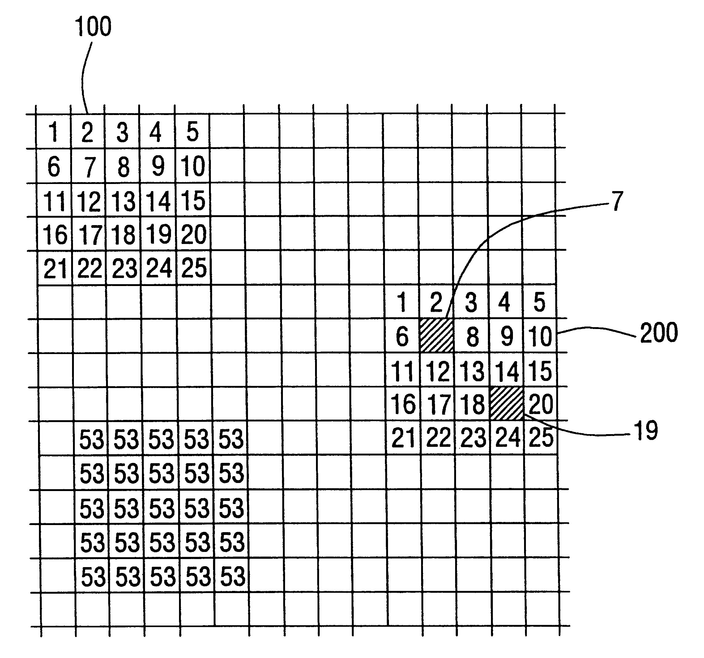
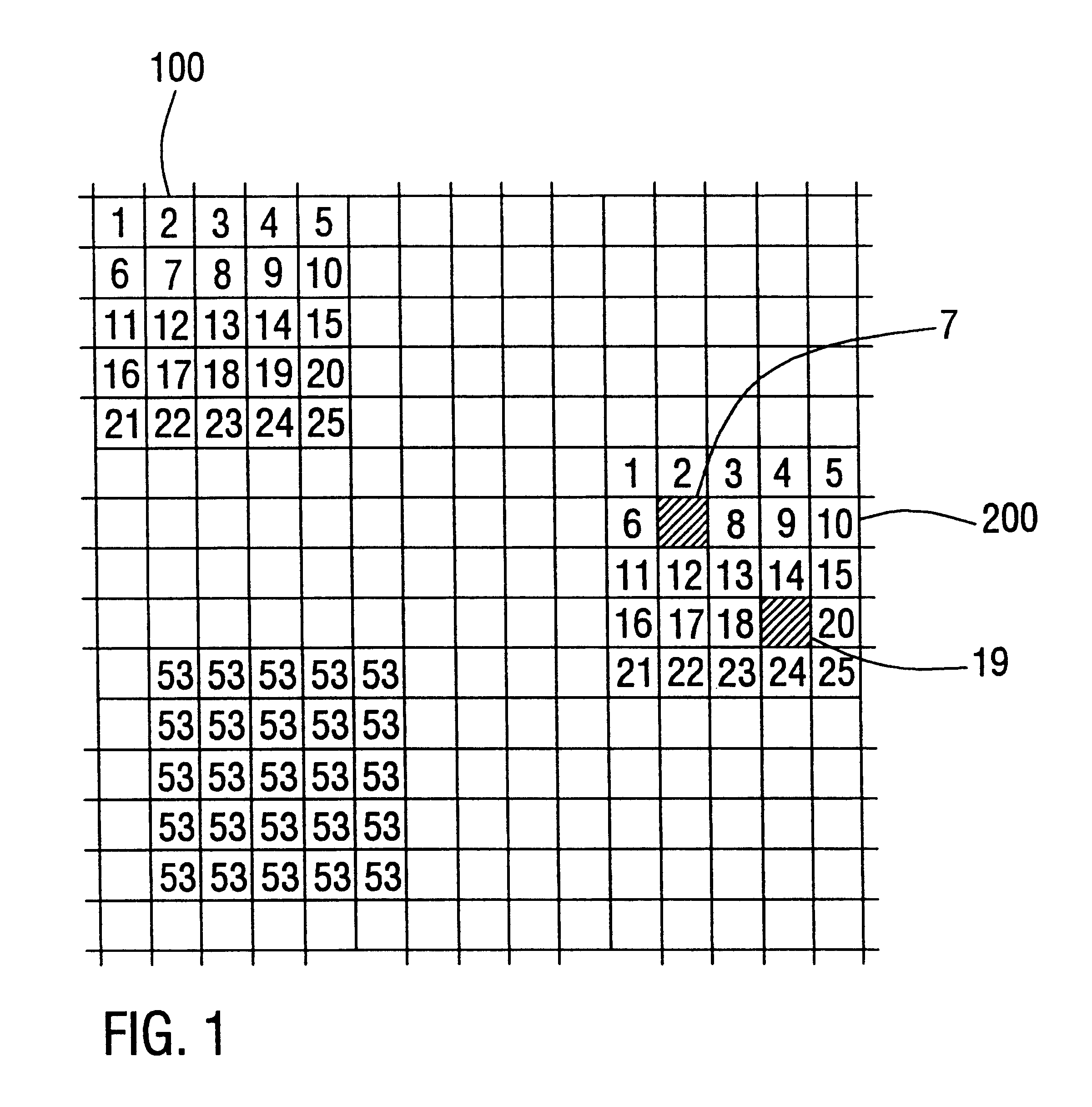
As has already been stated hereinbefore, the present invention makes use of a sensor with image elements which are markedly smaller than would be necessary for the desired local resolution. A detail of such a sensor is schematically shown in the only figure of the present application. As can be seen in this figure, a plurality of image elements 1 to 25 forms a so-called effective image element 100. In the embodiment shown in the figure, each effective image element is formed by 5.times.5 image elements. It is, however, apparent that this number only serves as an example, other distributions being likewise imaginable. The resolution of digital X-ray sensors is, however, typically limited to approx. 50 .mu.m so that the side length of an effective image element 100 is 50 .mu.m. It follows that, in the embodiment shown, the individual image elements 1 to 25 each have an area of 10 .mu.m.times.10 .mu.m.

As has already been explained hereinbefore with reference to the prior art, the image...


PUM


Abstract

In a method for imaging in digital dental radioscopy making use of a sensor array, the individual image elements of which are smaller than a desired local resolution so that a plurality of image elements forms a respective effective image element, first reference signals, which are generated by the image elements of the sensor array when said sensor array is not exposed to X-radiation, are initially detected. In addition, second reference signals, which are generated by the image elements of the sensor array when said sensor array is exposed to X-radiation, are detected. Subsequently, defective image elements are determined on the basis of the detected first and second reference signals, whereupon an image of an object is produced using exclusively the image elements that have been determined as being non-defective. Furthermore, during production of the image of an object, it can be determined for the object signals detected for the respective image elements whether said image elements have been hit directly by an X-ray quantum. Image elements that have been hit directly by an X-ray quantum are not used for producing the image of the object.

Description

1. Field of the InventionThe present invention relates to methods and devices for imaging in digital dental radioscopy, and especially to methods and devices making use of sensor arrays whose image elements are smaller than would be necessary for the desired local resolution.2. Description of Prior ArtDental X-ray diagnostic units in which images are produced digitally making use of CCD sensors (CCD =charge coupled device) have been known for some time. The sensors used normally comprise the CCD sensor itself and a scintillation layer which is applied directly to the CCD sensor and which converts the incident X-radiation into visible light which will then generate an electric charge in the underlying CCD sensor. The image information is then read from the CCD sensor by applying suitable clock signals, whereupon it is preprocessed, digitized and finally transmitted to a computer system, e.g. a personal computer, for display and storage. In comparison with a conventional film techniqu...

Claims


Application Information

Patent Timeline
IPC IPC(8): H04N5/217H04N5/321H04N5/325H04N5/367
CPCH04N5/325H04N5/367H04N25/68
Inventor SCHMITT, PETERKOSTKA, GUNTHERHANKE, RANDOLF
Owner FRAUNHOFER GESELLSCHAFT ZUR FOERDERUNG DER ANGEWANDTEN FORSCHUNG EV
Why Eureka
Try Eureka