Mechanical pipe coupling with toothed retainer

a technology of mechanical pipes and retainers, applied in the field of coupling, can solve the problems of exposing workers, affecting the work efficiency of workers, and disrupting the oxide layer, and achieve the effect of resisting axial rotation of pipes and low energy loss

Inactive Publication Date: 2002-12-31
VICTAULIC
View PDF40 Cites 158 Cited by
  • Summary
  • Abstract
  • Description
  • Claims
  • Application Information

AI Technical Summary

Benefits of technology

It is yet again another object of the invention to provide a coupling which causes low energy loss to fluid flowing through it.
It is still

Problems solved by technology

Next, the cleaned surfaces are coated with a flux material, usually an acid flux, which further disrupts the oxide layer (when heated) and permits metal to metal contact between the fitting, the pipe end and the solder.
Many steps are required to make the soldered joint, thus, it is a time consuming and labor intensive operation.
Furthermore, the solder often contains lead, and the flux, when heated, can give off noxious fumes, thus, exposing the worker to hazardous substances which can adversely affect health over time.
The joint is typically heated with an open gas flame which can pose a fire hazard.
While these mechanical couplings avoid the above identified problems associated with soldered joints, they can suffer from one or more of the following disadvantages.
The annular ring may not provide adequate pull-out strength, and the pipe end could be inadvertently separated from the coupling, for example, during thermal contraction of a long run made of several segments of mechanically coupled pipes.
If both ends of the pipe run are fixed the thermal contraction will put significant tension loads on each joint, tending to pull them a

Method used


Image

  • Mechanical pipe coupling with toothed retainer
  • Mechanical pipe coupling with toothed retainer
  • Mechanical pipe coupling with toothed retainer

Examples


Embodiment Construction

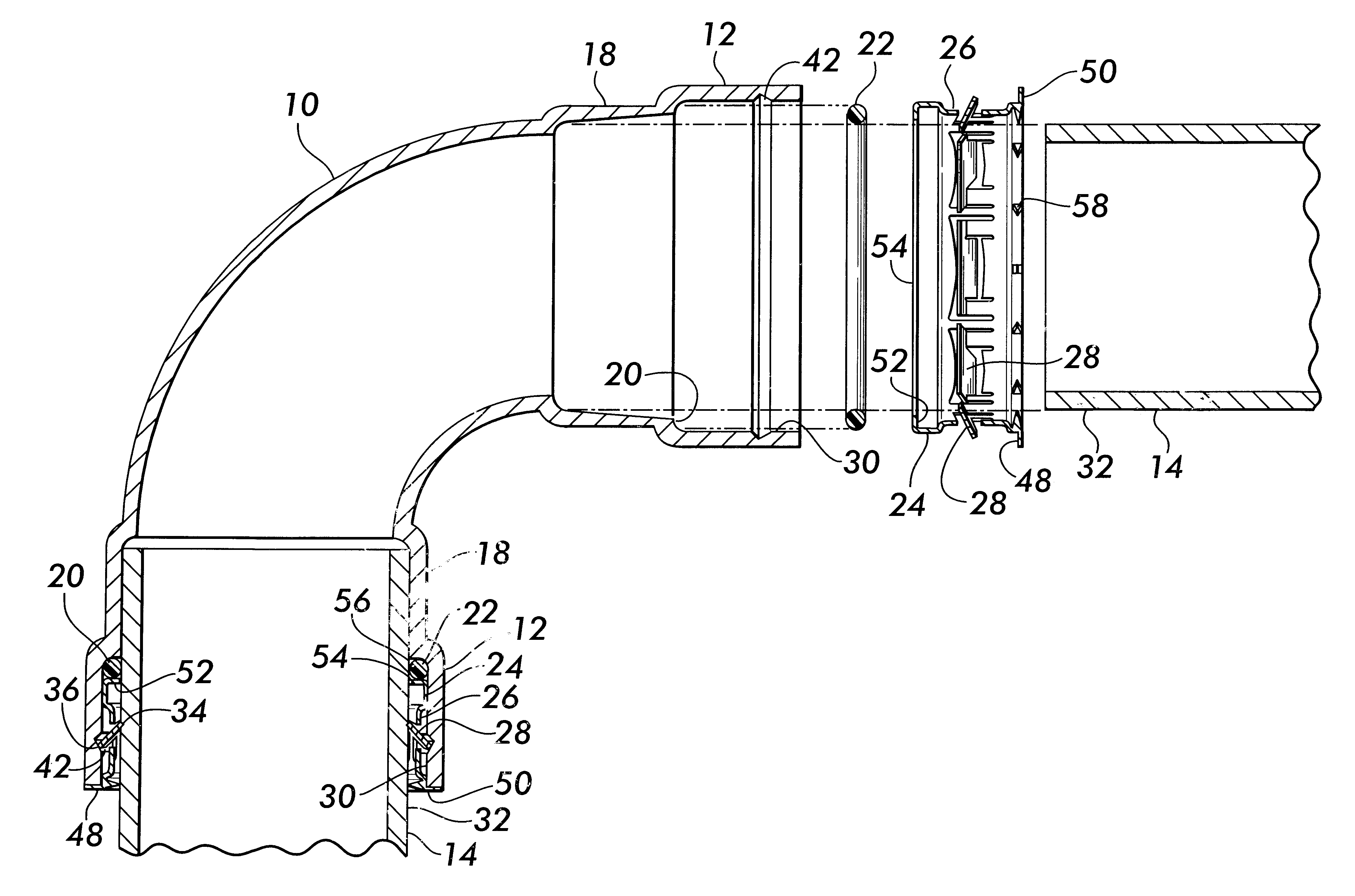
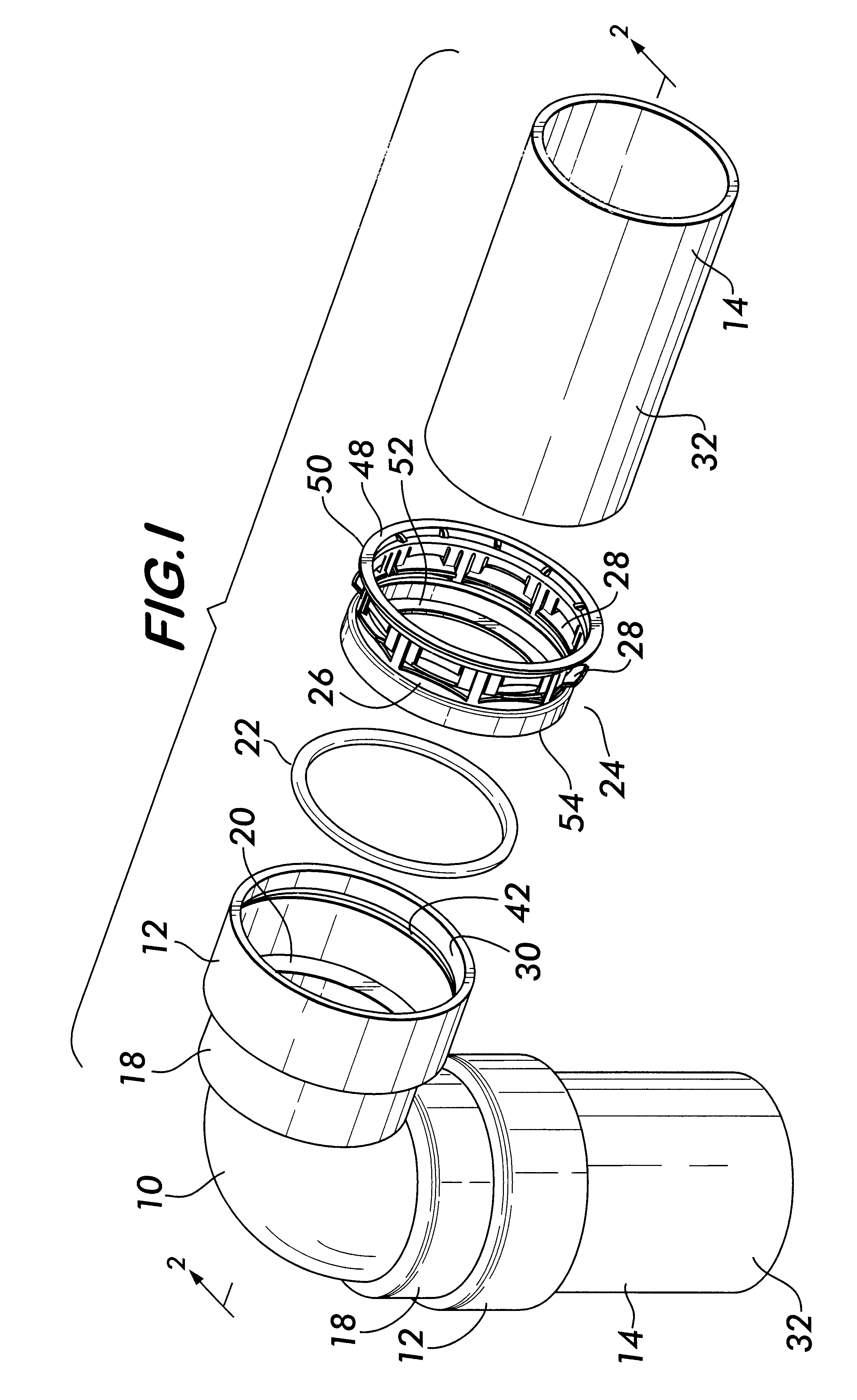
FIG. 1 shows the preferred embodiment of a coupling 10 according to the invention. The coupling 10 is depicted as a 90.degree. elbow by way of example, but could take any practical form such as a 45.degree. elbow, a tee, a straight coupling, a portion attached to a valve for coupling to a pipe end and the like.

The coupling 10 has a first receptacle 12, preferably cylindrical in shape, for coaxially receiving a pipe end 14. A second receptacle 18 is arranged coaxially and in tandem with first receptacle 12. Second receptacle 18 is preferably tapered, for example, with a linear taper, or a frusto-conical taper, but may also be cylindrical. The taper is preferred to allow second receptacle 18 to receive pipe end 14 in an interference fit thereby providing frictional resistance against axial rotation between said pipe and the coupling 10. Second receptacle 18 is smaller than first receptacle 12 so as to form a shoulder 20 between the first and second receptacles 12 and 18.

Coupling 10 ca...


PUM


Abstract

An open end of a standard pipe fitting is enlarged in diameter to coaxially receive an O-ring and a retainer having a cylindrical surface. A plurality of locking teeth project from the cylindrical surface and are engageable with both the inner surface of the fitting and an outer surface of a pipe end inserted coaxially into the fitting open end. Each of the locking teeth have oppositely disposed edges facing obliquely inwardly and outwardly to engage both the pipe end and the fitting and resisting motion of the pipe end relatively to the fitting. In an alternate embodiment, a first plurality of teeth each have an edge facing obliquely inwardly of the fitting to engage the pipe end and resist motion tending to withdraw the pipe end from the fitting. A second plurality of teeth each have an edge facing obliquely outwardly of the fitting and resist motion tending to withdraw the retainer from the fitting.

Description

This invention relates to couplings for pipes and especially to couplings which effect a strong, reliable joint with a fluid-tight seal without the need for brazing or soldering.The construction of piping networks requires couplings that can form fluid-tight joints between pipe ends which can withstand external mechanical forces, as well as internal fluid pressure and reliably maintain the integrity of the joint. Many forms of joints are known, such as brazed or soldered joints, threaded joints, welded joints and joints effected by mechanical means.For example, copper tubing, which is used extensively throughout the world to provide water service in homes, businesses and industry, is typically joined by means of couplings which are soldered to the pipe ends to effect a connection.The use of copper tubing for piping networks is so widespread that standard tubing sizes have been established in various countries. For example, in the U.S., there is the ASTM Standard entitled "Specificat...

Claims


Application Information

Patent Timeline
IPC IPC(8): F16L21/08
CPCF16L37/091F16L37/0915F16L37/0925
Inventor SNYDER, SR., RONALD R.WILK, JR., CHARLES E.THAU, JR., LAWRENCE W.DOLE, DOUGLAS R.
Owner VICTAULIC
Why Eureka
Try Eureka