Control of erosion profile and process characteristics in magnetron sputtering by geometrical shaping of the sputtering target

a technology of erosion profile and process characteristics, applied in the field of thin film deposition, can solve the problems of reducing the deposition rate of substrates

Inactive Publication Date: 2002-12-31
NOVELLUS SYSTEMS
View PDF23 Cites 48 Cited by
  • Summary
  • Abstract
  • Description
  • Claims
  • Application Information

AI Technical Summary

Benefits of technology

FIG. 1B is a schematic of a simple non-planar metallic target showing the redepostion of sputtered material.
FIG. 2 is a schematic of a non-p...

Problems solved by technology

Limitations, however, exist with the above-described methods.
Increasing the distance between the sputter source and the substrate generates material loses and lower deposition rate, and is considered very inefficient.
Similarly, when a collimating fil...

Method used


Image

  • Control of erosion profile and process characteristics in magnetron sputtering by geometrical shaping of the sputtering target
  • Control of erosion profile and process characteristics in magnetron sputtering by geometrical shaping of the sputtering target
  • Control of erosion profile and process characteristics in magnetron sputtering by geometrical shaping of the sputtering target

Examples


Embodiment Construction

)

In describing the preferred embodiment of the present invention, reference will be made herein to FIGS. 1-12 of the drawings in which like numerals refer to like features of the invention. Features of the invention are not necessarily shown to scale in the drawings.

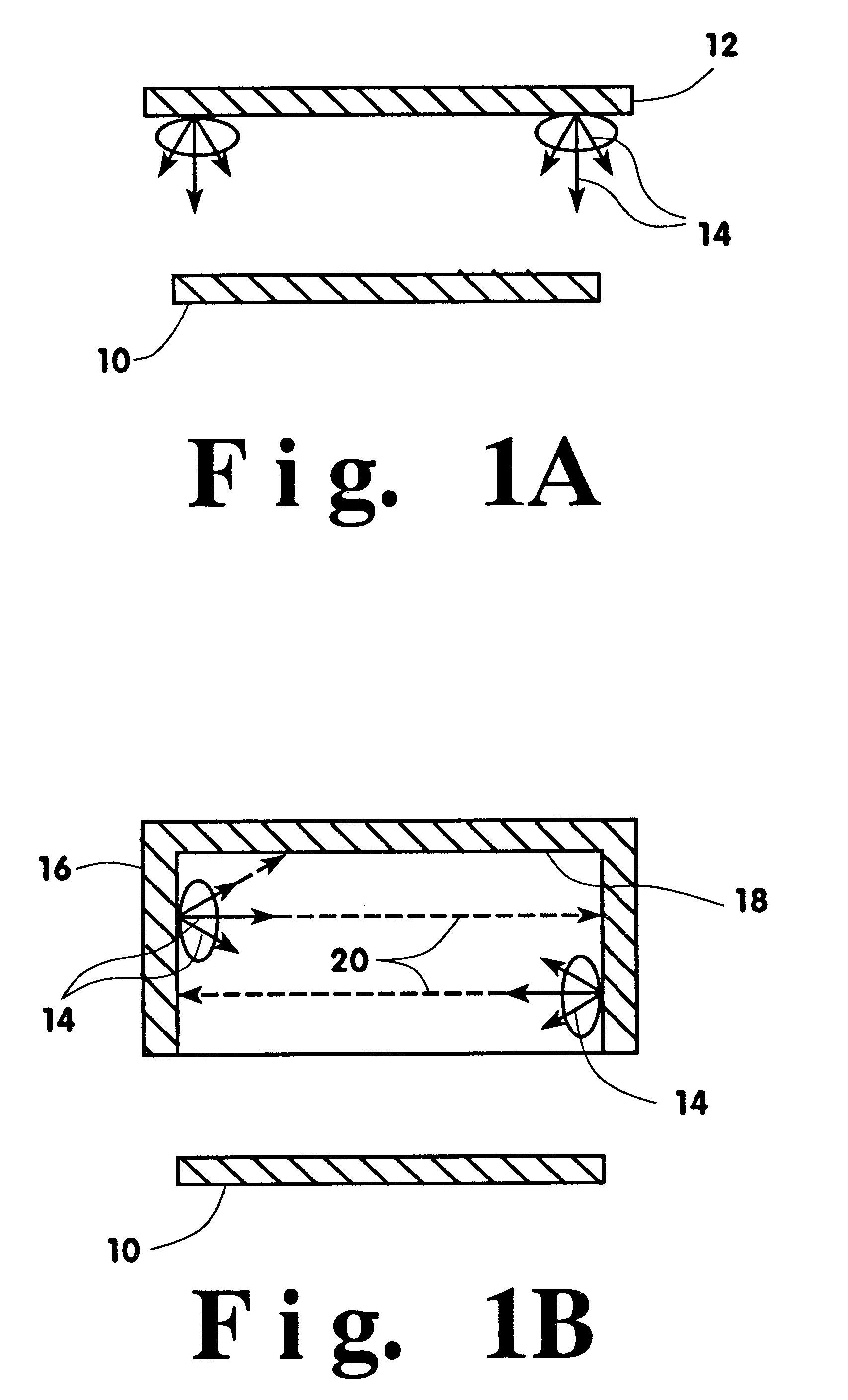
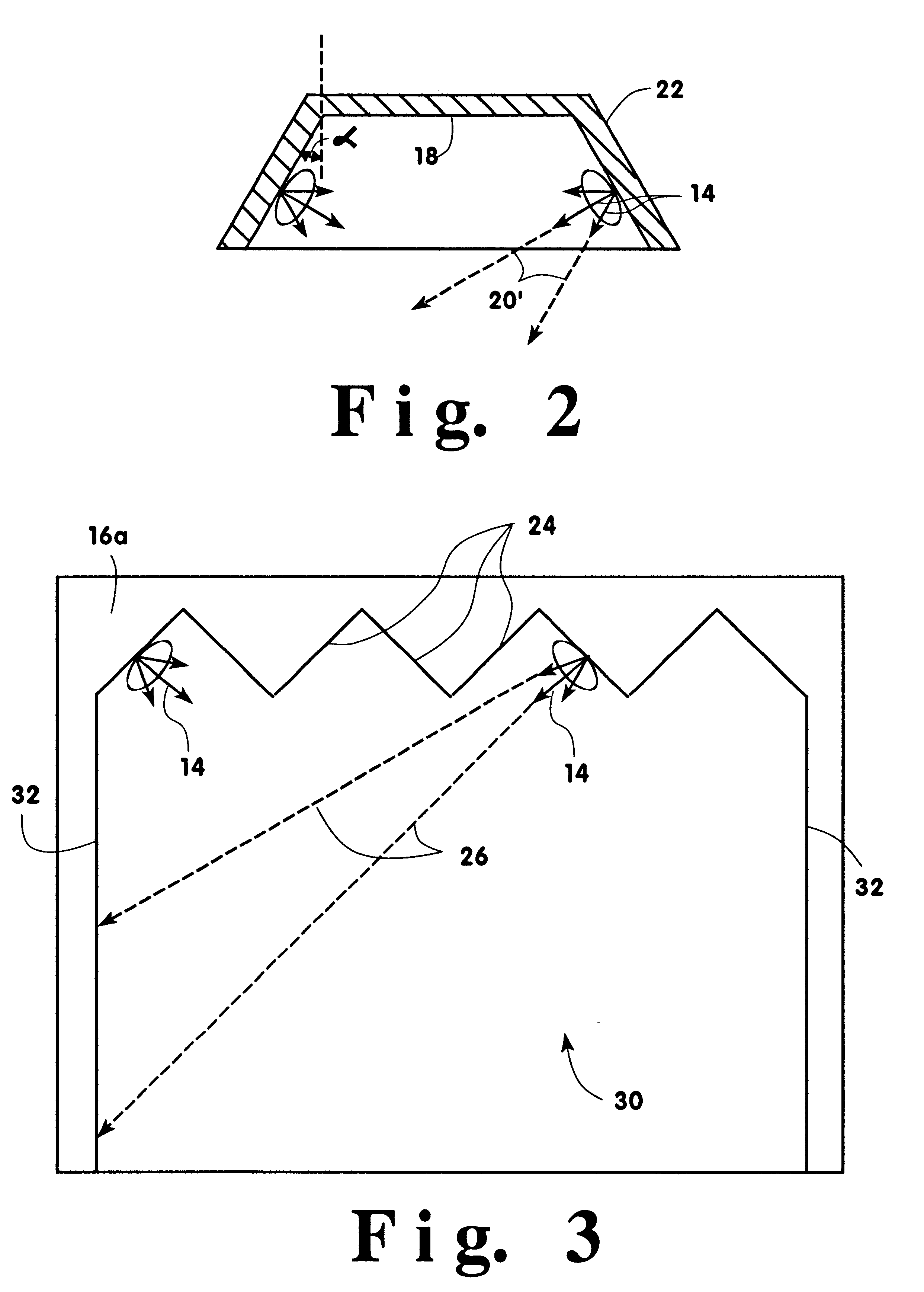
To achieve uniform erosion, where erosion is considered the net removal of material of a physical vapor deposition sputtering target, traditionally, a magnetic circuit is designed such that it can be rotated behind the target to sweep all surfaces of the sputtering target by a high-density plasma. The ions from the plasma, usually an inert gas such as argon gas, are attracted to the target by the negative potential of the sputtering target, and material is sputtered, thereby eroding the target. Many different magnetic circuits are utilized to achieve this goal, as can be found in the prior art. While most sputtering targets are made in planar shape, recently, a new class of sputtering sources has been introduced in which...


PUM

PropertyMeasurementUnit
Magnetic fieldaaaaaaaaaa
Efficiencyaaaaaaaaaa
Surface areaaaaaaaaaaa

Abstract

An apparatus and method for controlling and optimizing a non-planar target shape of a sputtering magnetron system are employed to minimize the redeposition of the sputtered material and optimize target erosion. The methodology is based on the integration of sputtered material from each point of the target according to its solid angle view of the rest of the target. The prospective target's geometry is optimized by analytically comparing and evaluating the methodology's results of one target geometry against that of another geometry, or by simply altering the first geometry and recalculating and comparing the results of the first geometry against the altered geometry. The target geometries may be of many different shapes including trapezoidal, cylindrical, parabolic, and elliptical, depending upon the optimum process parameters desired. A sputtering system is developed using this methodology, having a main magnet stack, a rotating magnet, a target having selected target shapes optimized for controlling erosion, downstream magnets, a substrate, and an electric field induced plasma stream.

Description

1. Field of the InventionThe present invention relates to thin film deposition, and is particularly related to physical vapor deposition (PVD) of solid materials in connection with the fabrication of semiconductor integrated circuits. More particularly, this invention is related to a method for controlling the target erosion and process characteristics in a physical vapor deposition sputtering source. This invention relates to any sputtering source utilizing sputtering targets. However, specific teachings and examples will be given which relate to magnetron sputtering, and especially to hollow cathode magnetron (HCM) sputtering sources.2. Description of Related ArtIn a sputtering device, a target is subjected to bombardment by high energy ions to dislodge and eject material from the target onto a workpiece, such as a semiconductor wafer. A concise description of the related art of sputtering devices can be found in U.S. Pat. No. 4,198,283, issued to Class, et al., on Apr. 15, 1980, ...

Claims


Application Information

Patent Timeline
IPC IPC(8): C23C14/34H01J37/32H01J37/34
CPCC23C14/3407H01J37/3405H01J37/3423H01J37/347
Inventor ASHTIANI, KAIHAN A.HARTSOUGH, LARRY D.HILL, RICHARD S.LEVY, KARL B.MARTINSON, ROBERT M.
Owner NOVELLUS SYSTEMS
Why Eureka
Try Eureka