
Spread-spectrum clock buffer/driver that modulates clock period by switching loads

a clock buffer and clock period technology, applied in the field of integrated circuits, can solve the problems of electromagnetic radiation that affects intentional receivers, can often be influenced by unintentional transmitters, and can cause disturbances in other electronic equipment,

Inactive Publication Date: 2002-12-31
DIODES INC
View PDF24 Cites 96 Cited by
  • Summary
  • Abstract
  • Description
  • Claims
  • Application Information

AI Technical Summary

Problems solved by technology

Electronic devices and equipment can often generate interference that creates disturbances in other electronic equipment.
For example, a portable computer may emit radiation that interferes with a television receiver.
Intentional receivers, such as televisions, cellular phones, pagers, and wireless devices, are often affected by unintentional transmitters that emit electromagnetic radiation.
As both types of electronic equipment become more common, interference becomes more noticeable to the consumer.
Portable devices such as portable personal computers (PC's) are particularly problematic since these portable devices are easily placed near televisions or other receivers.
Since radiation rapidly increases with smaller distances, smaller and more portable equipment often appear to generate more interference.
Improving technology also worsens the EMI problem.
Higher communication rates require that more data bits be transferred in a time period; a higher clock rate and more interference results.
Unfortunately, noise and tracking can be a problem, especially when a clock generator and multiple clock buffer drivers are cascaded.
Such a fixed-frequency clock could generate an unacceptable amount of EMI.
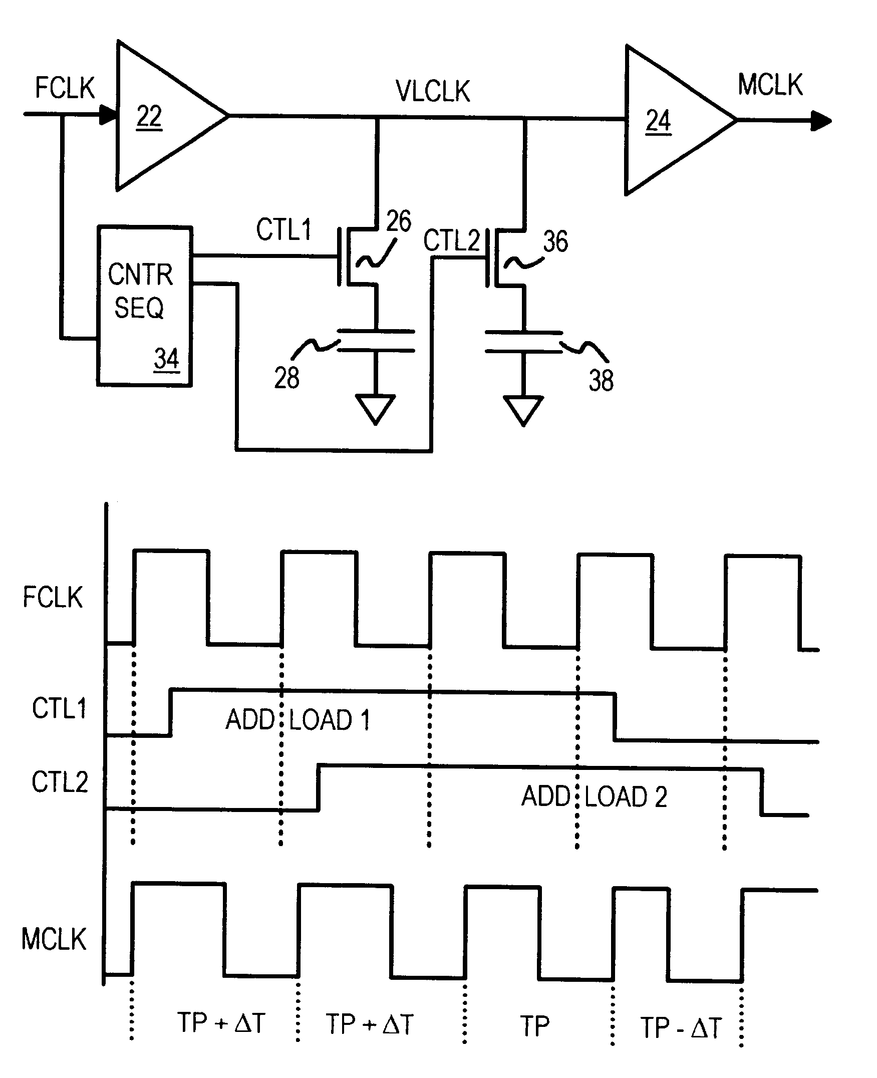
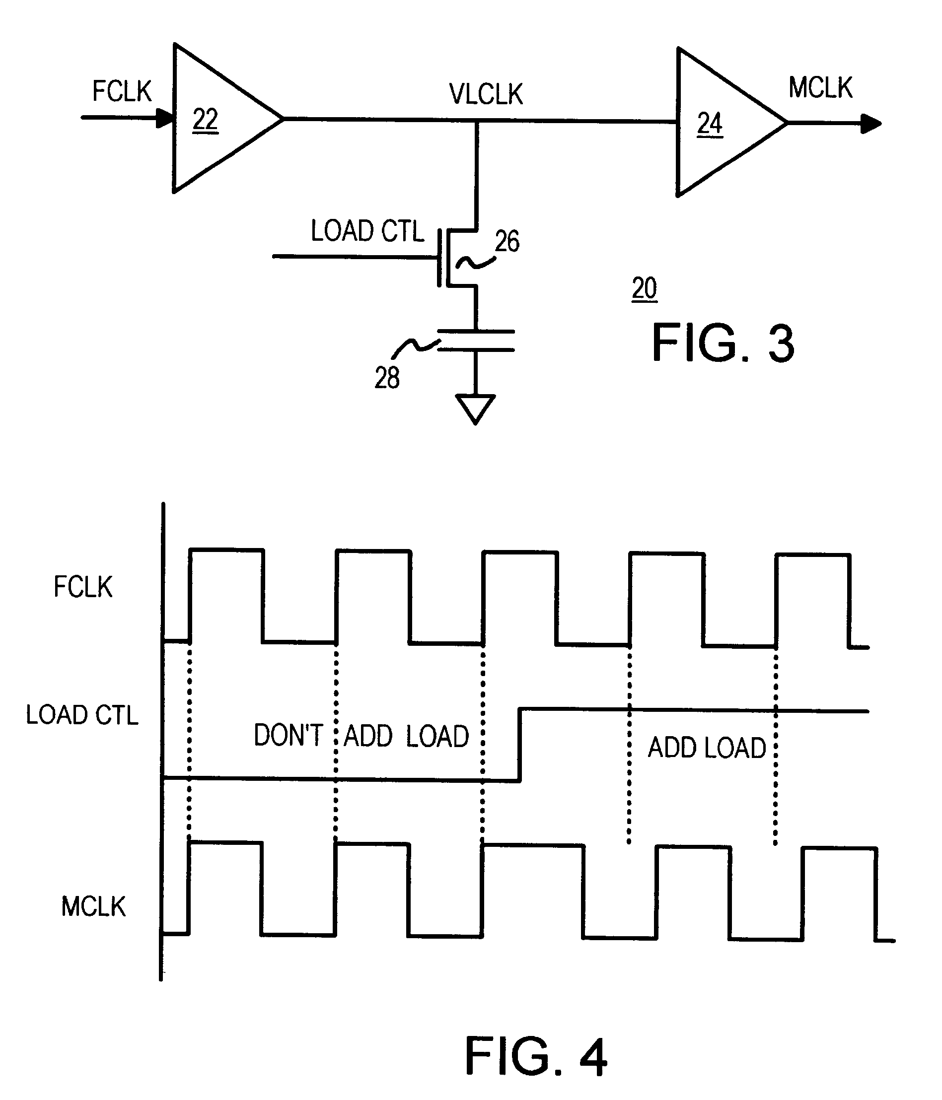
However, LOAD_CTL is high when the first falling edge of FCLK occurs, so the first falling edge of MCLK is delayed by the added capacitance.

Method used


Image

  • Spread-spectrum clock buffer/driver that modulates clock period by switching loads
  • Spread-spectrum clock buffer/driver that modulates clock period by switching loads
  • Spread-spectrum clock buffer/driver that modulates clock period by switching loads

Examples


Embodiment Construction

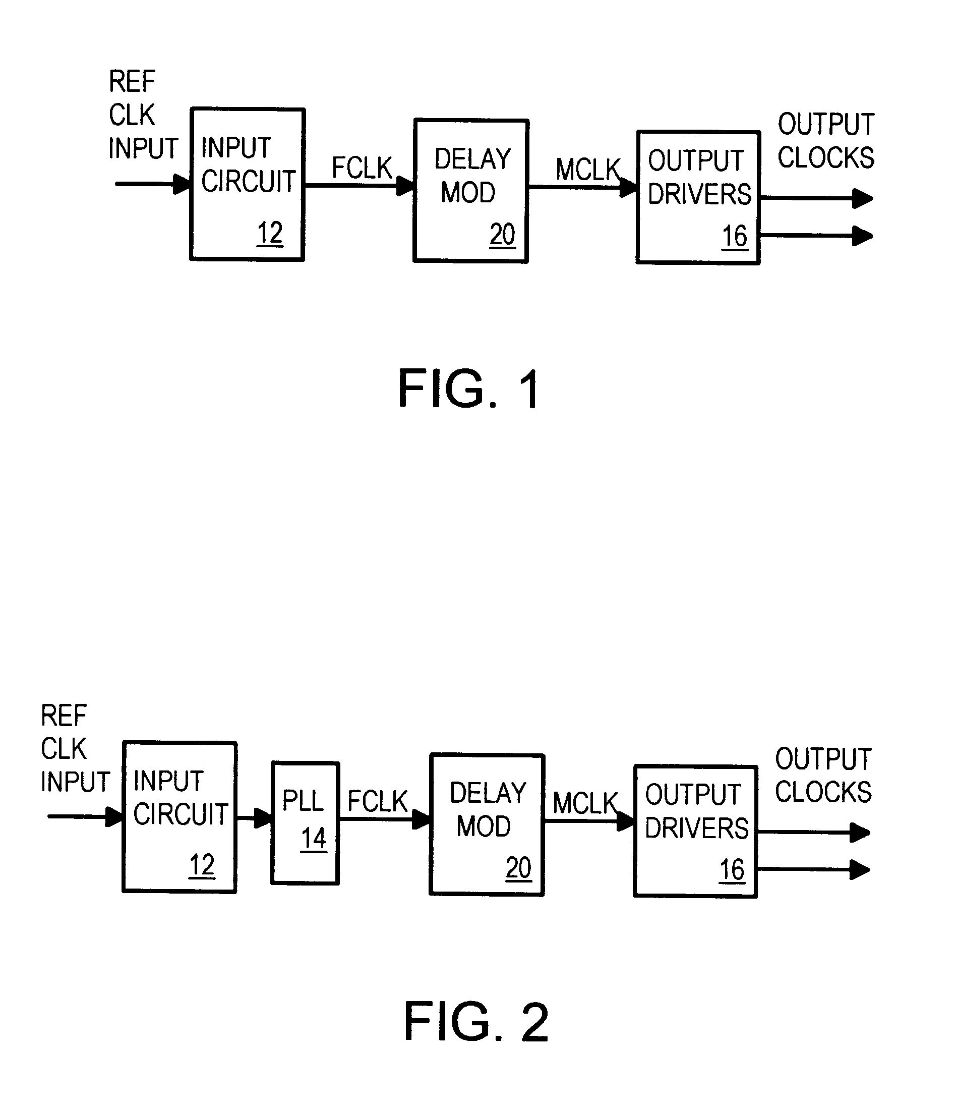
Several other embodiments are contemplated by the inventor. Output drivers 16 can include branching logic to generate multiple copies of MCLK that drive different parts of a system, such as a memory clock to a clocked DRAM and a processor clock to a microprocessor that are both based on the same reference clock. More complex clock-dividing and power-down clock disabling logic can be included in output drivers 16. Either inverting or non-inverting buffers can be used for the input circuit, output drivers, and buffers in the clock modulator. The sequencer can be clocked by either the rising or falling edge of FCLK, or by a derivative of FCLK. The sequencer clock and FCLK could each be derived from a common upstream input clock.

A p-channel load-switching transistor could be substituted, or both a p-channel and an n-channel transistor could be used in parallel as a transmission gate to switch the clock load on and off. Other transistors, resistors, or capacitors could be added in parall...


PUM


Abstract

A clock modulator spreads the frequency spectrum of an input clock to generate an output clock. A capacitor is connected to an intermediate clock node by a load-switching transistor. When the transistor is turned on, the capacitor increases the loading on the intermediate clock node, increasing delay. When the transistor is turned off, the delay is reduced. Output clock cycle periods are extended when delay is added, and reduced when the transistor turns off. A counter or sequencer is clocked by the input clock and drives the load-switching transistor. The transistor is turned on and off for alternate cycles when the counter is a toggle flip-flop, spreading the frequency over two frequencies every two clock cycles. Two capacitors of different sizes, connected to the intermediate clock node by two transistors, can be switched by a 2-bit sequencer, spreading the output clock over 7 frequencies every 7 clock cycles.

Description

BACKGROUND OF INVENTIONThis invention relates to integrated circuits, and more particularly to clock buffers and drivers with reduced EMI.Electronic devices and equipment can often generate interference that creates disturbances in other electronic equipment. For example, a portable computer may emit radiation that interferes with a television receiver. Intentional receivers, such as televisions, cellular phones, pagers, and wireless devices, are often affected by unintentional transmitters that emit electromagnetic radiation. As both types of electronic equipment become more common, interference becomes more noticeable to the consumer.Electromagnetic interference (EMI) is a measure of the amount of interference that an electronic device (the unintentional transmitter) disturbs an intentional receiver. Government agencies such as the Federal Communication Commission (FCC) strictly regulate the amount of radiation or EMI that an electronic device can generate. Portable devices such a...

Claims


Application Information

Patent Timeline
IPC IPC(8): H03K5/13H04B15/04H04B15/02H03K5/00
CPCH03K5/133H04B15/04H03K2005/00071H04B2215/064H04B2215/067
Inventor YEN, YAO TUNG
Owner DIODES INC
Learn More