Liquid crystal display element and a display device having a homeotropic alignment

a liquid crystal display element and display device technology, applied in the direction of polarising elements, identification means, instruments, etc., can solve the problems of reducing the aperture rate as the rate of the aperture occupying one pixel, reducing the quality of the image, and reducing the contrast ratio of light leakag

Inactive Publication Date: 2002-12-31
PANASONIC LIQUID CRYSTAL DISPLAY CO LTD +1
View PDF13 Cites 21 Cited by
  • Summary
  • Abstract
  • Description
  • Claims
  • Application Information

AI Technical Summary

Benefits of technology

In addition, in the transmission type liquid crystal light valve, in order to prevent the generation of the flicker due to the slight overlap of the D.C. voltages, the driving is carried out in such a way that the applied voltages to the adjacent pixels are opposite in polarity to each other. Moreover, since the lateral electric field is generated in the region between the adjacent pixels in which the applied voltages thereto are opposite in polarity to each other, the alignment of the liquid crystal goes out of order in that region. This, for example, results in the reduction of the contrast ratio of the leakage of light.
For this reason, in the transmission type liquid crystal light valve, the light is shut off for the region in which the alignment of the liquid crystal goes out of order, thereby preventing the reduction of the contrast ratio. However, this measures leaves the problem that the aperture rate as the rate which the aperture occupies in one pixel is largely reduced.
It is therefore another object of the present invention to provide a liquid crystal display device in which the high contrast ratio can be obtained.

Problems solved by technology

The phenomenon is particularly remarkable in the moving image, which reduces remarkably the quality of the image.
This, for example, results in the reduction of the contrast ratio of the leakage of light.
However, this measures leaves the problem that the aperture rate as the rate which the aperture occupies in one pixel is largely reduced.
However, if the liquid crystal molecules are inclined, then the retardation is generated.

Method used


Image

  • Liquid crystal display element and a display device having a homeotropic alignment
  • Liquid crystal display element and a display device having a homeotropic alignment
  • Liquid crystal display element and a display device having a homeotropic alignment

Examples


first embodiment

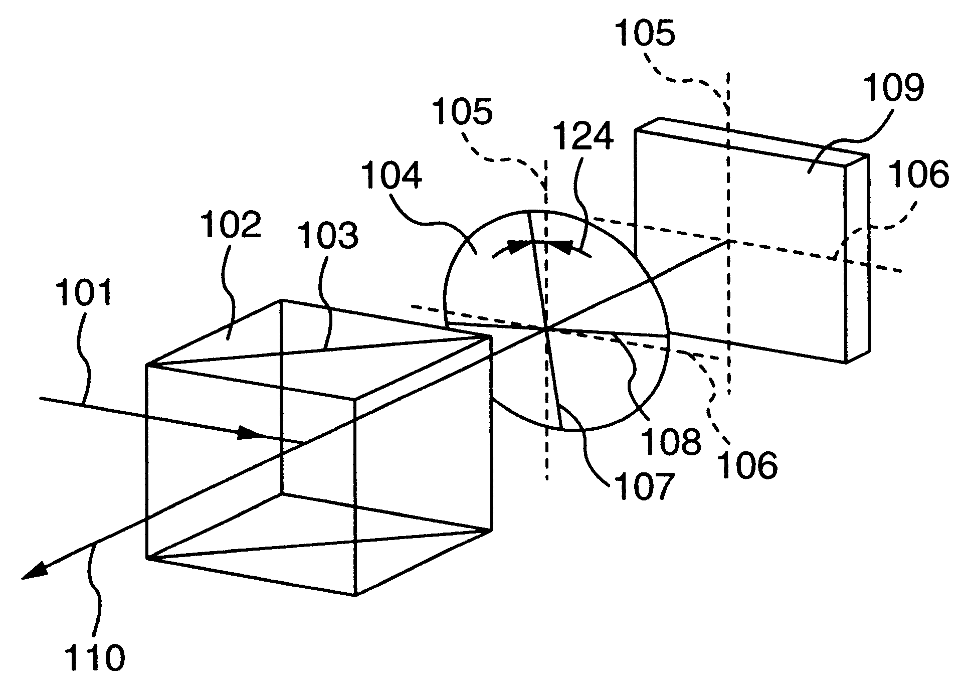
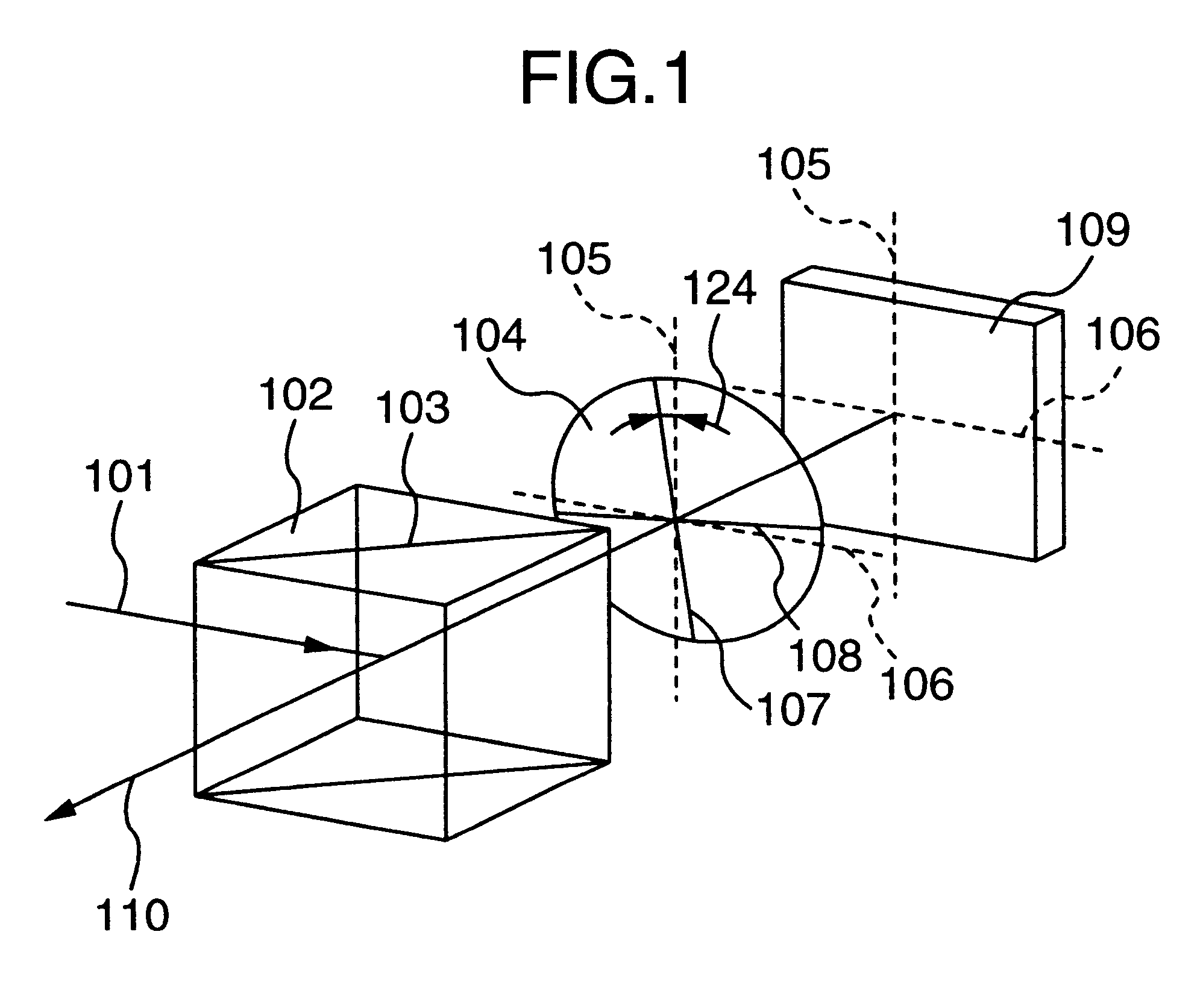
FIG. 1 is a diagram showing the relationship among the optical axes of optical elements in a liquid crystal display device of the present invention.

By the way, this liquid crystal display device can be applied to the products such as a liquid crystal projector and a liquid crystal television.

In FIG. 1, for the sake of simplicity of the description, there are shown only a reflection type liquid crystal light valve 109, a retardation plate 104, and a polarizing beam splitter 102.

By the way, the reflection type liquid crystal light valve 109 is connected to a liquid crystal driving driver (not shown) for driving this light valve 109, and the liquid crystal driving driver suitably drives a liquid crystal layer in accordance with the image information inputted thereto.

The polarizing beam splitter 102 is used as a polarizing element which serves as a polarizer as well as an analyzer, and is constructed by sticking two prisms to each other. Thus, the polarizing beam splitter 102 has the pr...

second embodiment

In a second embodiment, the twisted nematic alignment is applied to the liquid crystal layer.

First of all, the optical arrangement will hereinbelow be described with reference to FIG. 3.

FIG. 3 is a diagram showing the relative relationship among the optical axes when viewed from the vertical direction with respect to the liquid crystal panel. Then, the transparent substrate lies on this side, and the reflection substrate lies on the inside. Now, the alignment direction of the liquid crystal on the transparent substrate is defined as a first alignment direction 120 of the liquid crystal, the alignment direction of the liquid crystal on the reflection substrate is defined as a second alignment 121 of the liquid crystal, and the angle between the first and second liquid crystal alignment directions 120 and 121, i.e., the tortion angle of the liquid crystal is defined as a twisted angle 122. By the way, with respect to the sign of the twisted angle 122, the counterclockwise direction is...

third embodiment

In a third embodiment, the tilted homeotropic alignment is applied as the liquid crystal layer.

FIG. 15 shows the concrete optical arrangement of the third embodiment. Also, FIG. 15, similarly to FIG. 3, shows the relative relationship of the optical axes when viewed from the vertical direction with respect to the liquid crystal panel. In the third embodiment, the twisted angle is 0 degree, and the alignment angle is generally 45 degrees.

First of all, the description will hereinbelow be given with respect to the problem of the disorder of the liquid crystal alignment due to the lateral electric field in the region between the adjacent pixels.

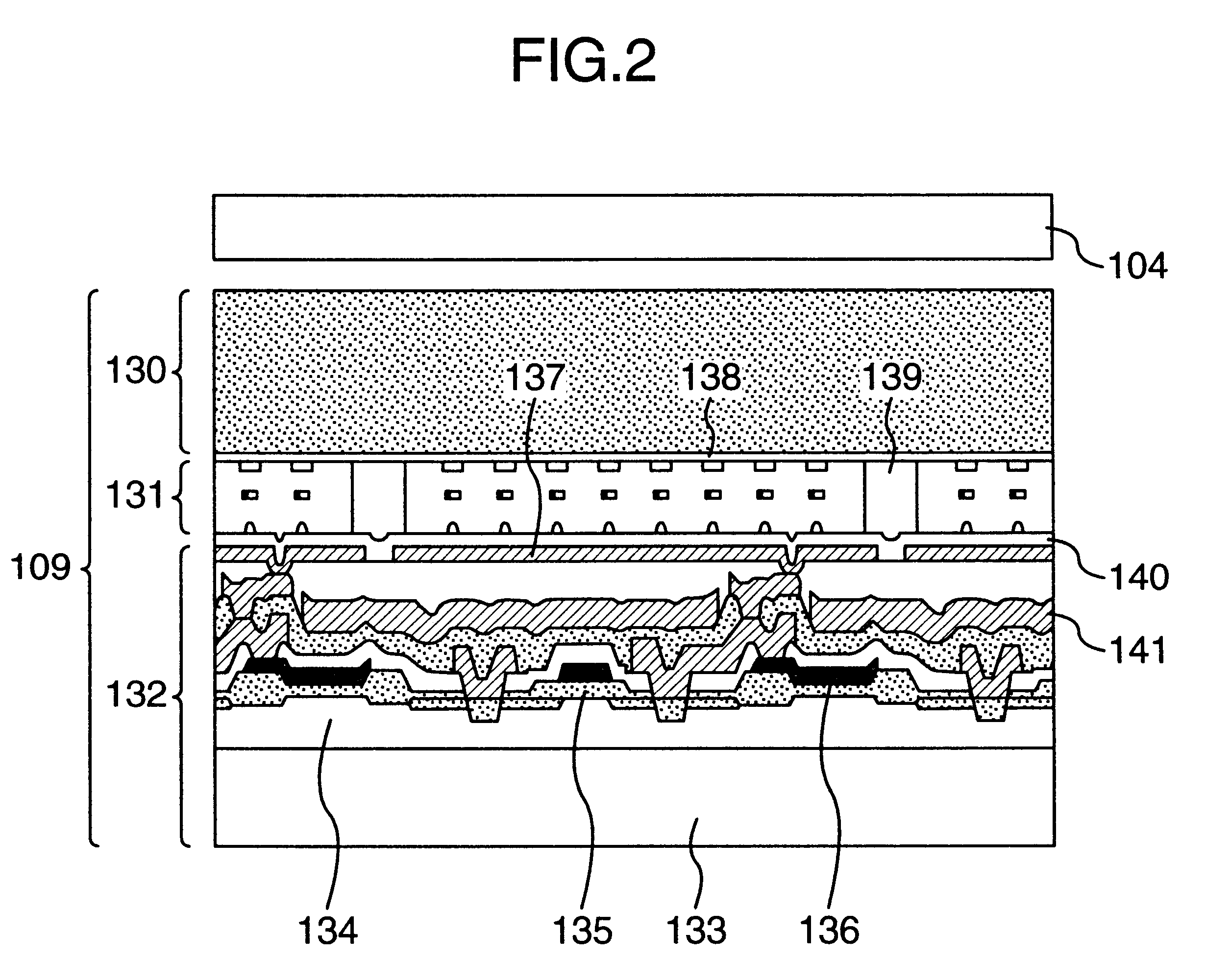
FIG. 16A and FIG. 16B are respectively cross sectional views of the liquid crystal light valve. Then, the transparent electrode 138 is formed on the glass substrate 130 facing the liquid crystal layer of the liquid crystal light valve, and the reflection electrode 137 is formed on the side of the active matrix substrate 132 facing the liquid crys...


PUM

PropertyMeasurementUnit
angleaaaaaaaaaa
angleaaaaaaaaaa
angleaaaaaaaaaa

Abstract

A liquid crystal display-element which has the high speed response and the high contrast and a display device employing the same are provided. In a display device employing a reflection type liquid crystal light valve, a retardation of a retardation plate which is provided between a polarizing element such as a polarizing beam splitter and the reflection type liquid crystal light valve is generally made ¼ of the wavelength of the incident light, and an optical axis (a slow axis or a fast axis) of the retardation plate and the polarizing direction of the incident polarized light are shifted from each other by slightly larger than 0 degree in order to arrange such optical elements.

Description

1. Field of the InventionThe present invention relates to a liquid crystal display element and a liquid crystal display device employing the same, e.g., a liquid crystal projector.2. Description of the Related ArtThe liquid crystal display modes for the reflection type liquid crystal light valve employing a nematic liquid crystal are roughly classified into the three kinds of systems. That is, there are a tilted homeotropic ECB (Electrically Controlled Birefringence) mode, a homogenious ECB mode and a reflection type twisted nematic mode.By the tilted homeotropic ECB mode is meant the alignment system in which the liquid crystal molecules are arranged in such a way as to be slightly inclined with respect to the perpendicular direction of each of a pair of substrates by utilizing the oblique evaporation method or the like, and this mode is described in an article of Applied Physics Letters 20, 199 (1972) for example.By the homogenious ECB mode is meant the alignment system in which t...

Claims


Application Information

Patent Timeline
Patent Type & Authority Patents(United States)
IPC IPC(8): G02F1/13G02F1/1335G02F1/139G02B5/30G02F1/13363G03B21/00G03B21/14G09F9/00
CPCG02F1/13363G02F1/1393G02F1/1396G02F2001/133531G02F2001/133638G02F2202/40G02F2203/02G02F2413/01G02F2413/08G02F1/133531G02F1/133638G02F1/1335
Inventor HIROTA, SHOICHIAOTO, KATSUHIDETSUMURA, MAKOTOTAKEMOTO, IWAO
Owner PANASONIC LIQUID CRYSTAL DISPLAY CO LTD
Why Eureka
Try Eureka