Two-part riveting apparatus and method for riveting barrel-shaped components such as aircraft fuselage components

a barrel-shaped component and aircraft fuselage technology, which is applied in metal working apparatus, metal-working machine components, manufacturing tools, etc., can solve the problems of difficult and complicated or even impossible to properly arrange the respective machine guide arrangements for forming rivets at particular individual rivet locations, and can only be used in a limited field of applications

Inactive Publication Date: 2003-01-14
AIRBUS OPERATIONS GMBH
View PDF28 Cites 73 Cited by
  • Summary
  • Abstract
  • Description
  • Claims
  • Application Information

AI Technical Summary

Benefits of technology

In the present apparatus, the inner part and the outer part are each supported independently of the manufactured product including the barrel-shaped structure being assembled, and are independently movable and arrangeable under a computer aided guidance relative to the manufactured product. Either the inner part and the outer part of the apparatus, or the manufactured product itself, may be movable relative to the other in the longitudinal X-direction. In this manner, each individual part of the apparatus, i.e. the outer part and the inner part, can be moved as necessary and the tools can be oriented and positioned with the required degrees of freedom of motion so as to efficiently move or reach around any obstructions and thereby reach difficult to access rivet locations in a fully automatic manner. This makes it possible to achieve an economically advantageous riveted seam fabrication of curved, large surface area components to form a barrel-shaped structure such as an aircraft fuselage.

Problems solved by technology

It is a disadvantage of this known automatic riveting robot that it can only be used in a limited field of applications due to its high structural mass.
A further disadvantage is that only certain rivet connections can be produced by this conventional automatic riveting robot, because the riveting systems are not individually movable in all spacial axes.
Further disadvantages result because the workpieces, for example aircraft fuselage shell components, must be slidingly pushed or advanced in the X-axis direction during the riveting process, which requires a rather heavy and complicated holding jig or support frame structure for precisely positioning the large workpieces.
However, in practice, it is very difficult and complicated or even impossible to properly arrange the respective machine guide arrangements for forming rivets at particular individual rivet locations, especially in the area within an aircraft fuselage for forming a lengthwise or transverse seam of the fuselage.
This is especially true because the interior of the fuselage shell comprises frames, stringers, spars, ribs and struts and the like, which represent obstacles or obstructions around which the machine guide arrangement and the respective tool units must be moved, and which in some cases completely block access to the required rivet locations.
This limits the mobility of the apparatus relative to the fuselage.
Instead, a crane is necessary to lift the outer apparatus and move it from one circumferential fuselage joint to the next, and therefore the system is not suited to riveting longitudinal joints.
Moreover, the known arrangement must have its crescent-shape adapted exactly to the contour of the particular type of fuselage being assembled, and presents the danger that the weight of the two apparatus will deform or misalign the aircraft sections being joined.
Other known systems in which the inner and / or outer riveting apparatus are mounted and supported on the fuselage itself suffer the same disadvantages.

Method used


Image

  • Two-part riveting apparatus and method for riveting barrel-shaped components such as aircraft fuselage components
  • Two-part riveting apparatus and method for riveting barrel-shaped components such as aircraft fuselage components
  • Two-part riveting apparatus and method for riveting barrel-shaped components such as aircraft fuselage components

Examples


Embodiment Construction

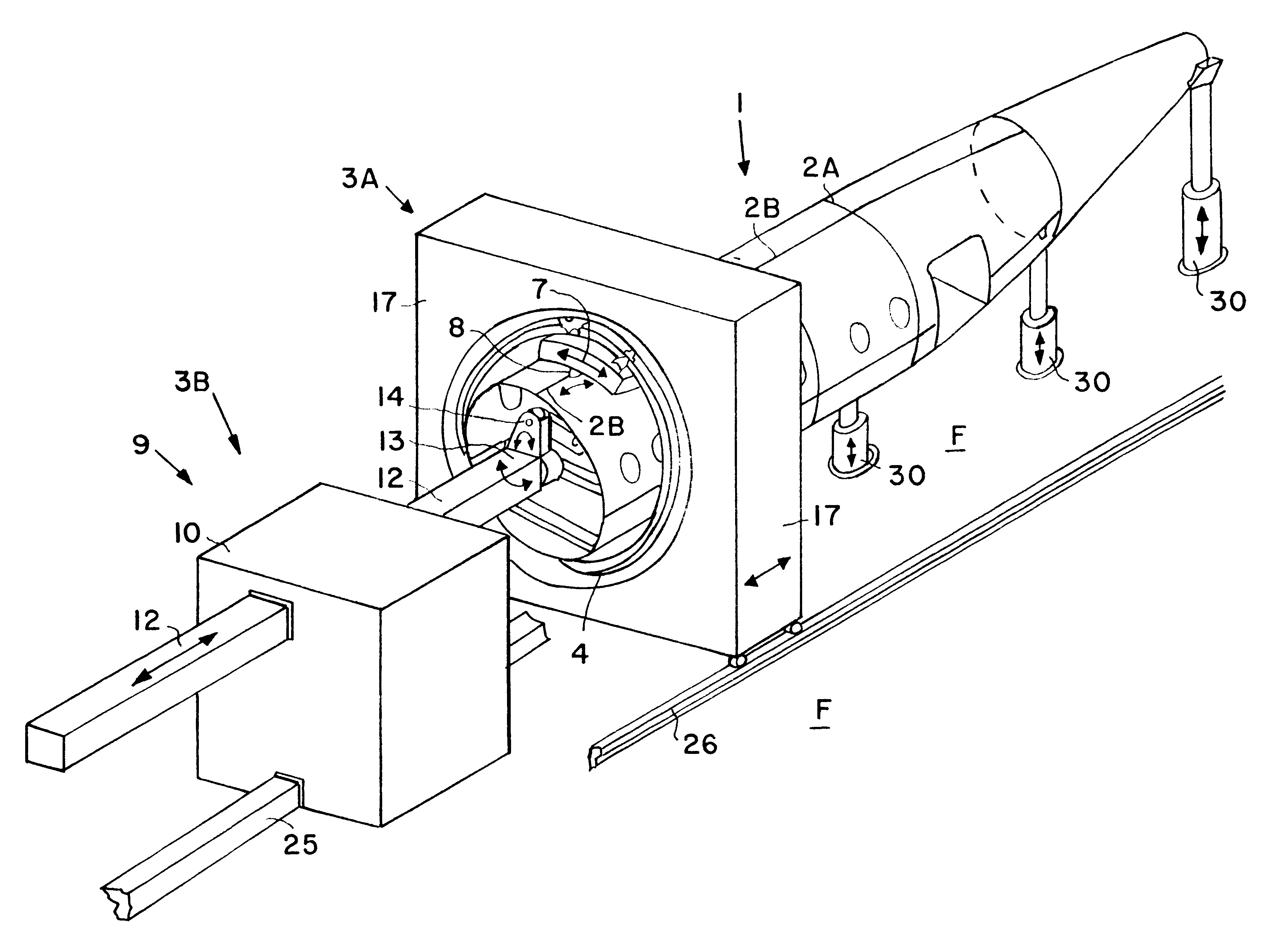
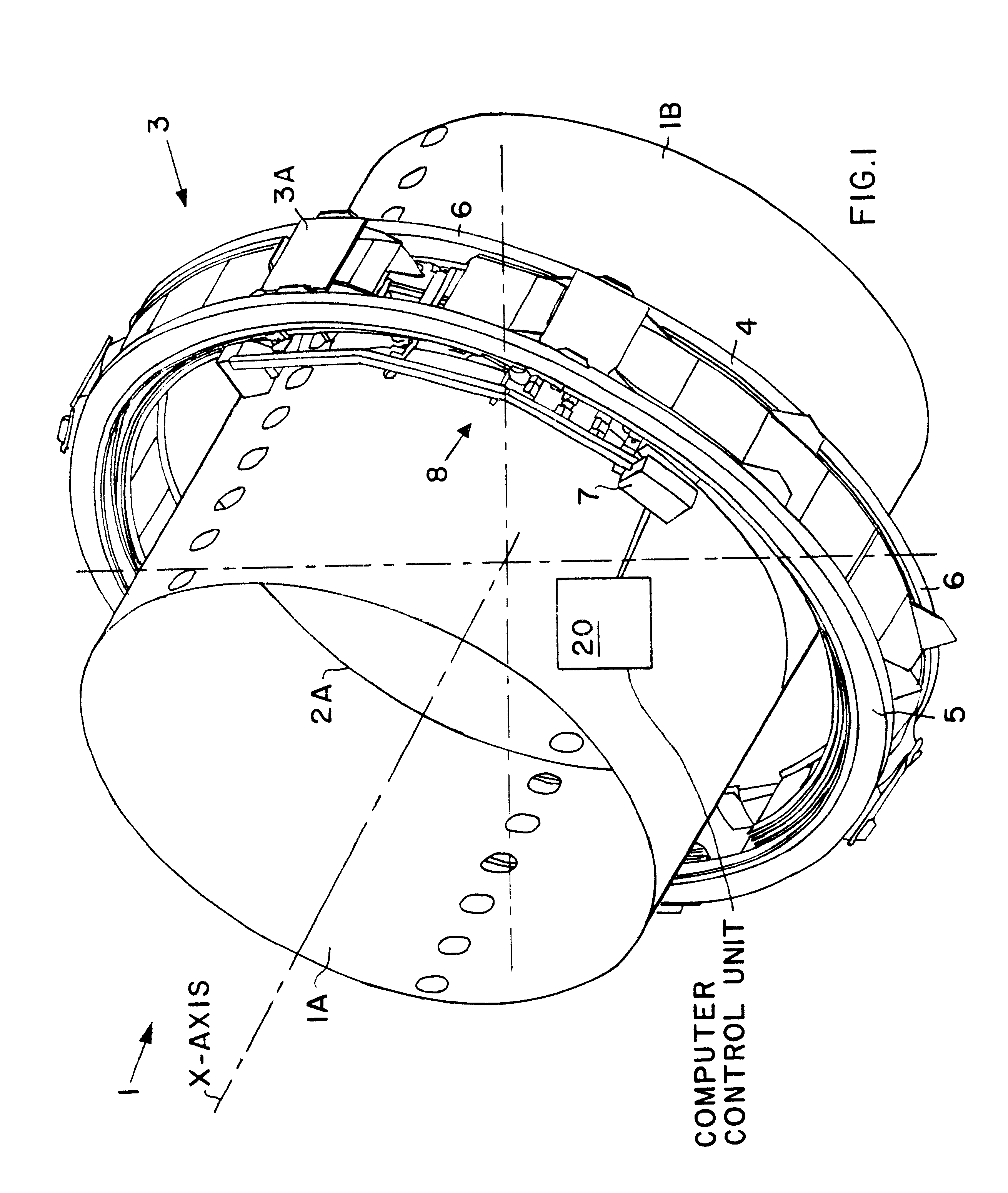
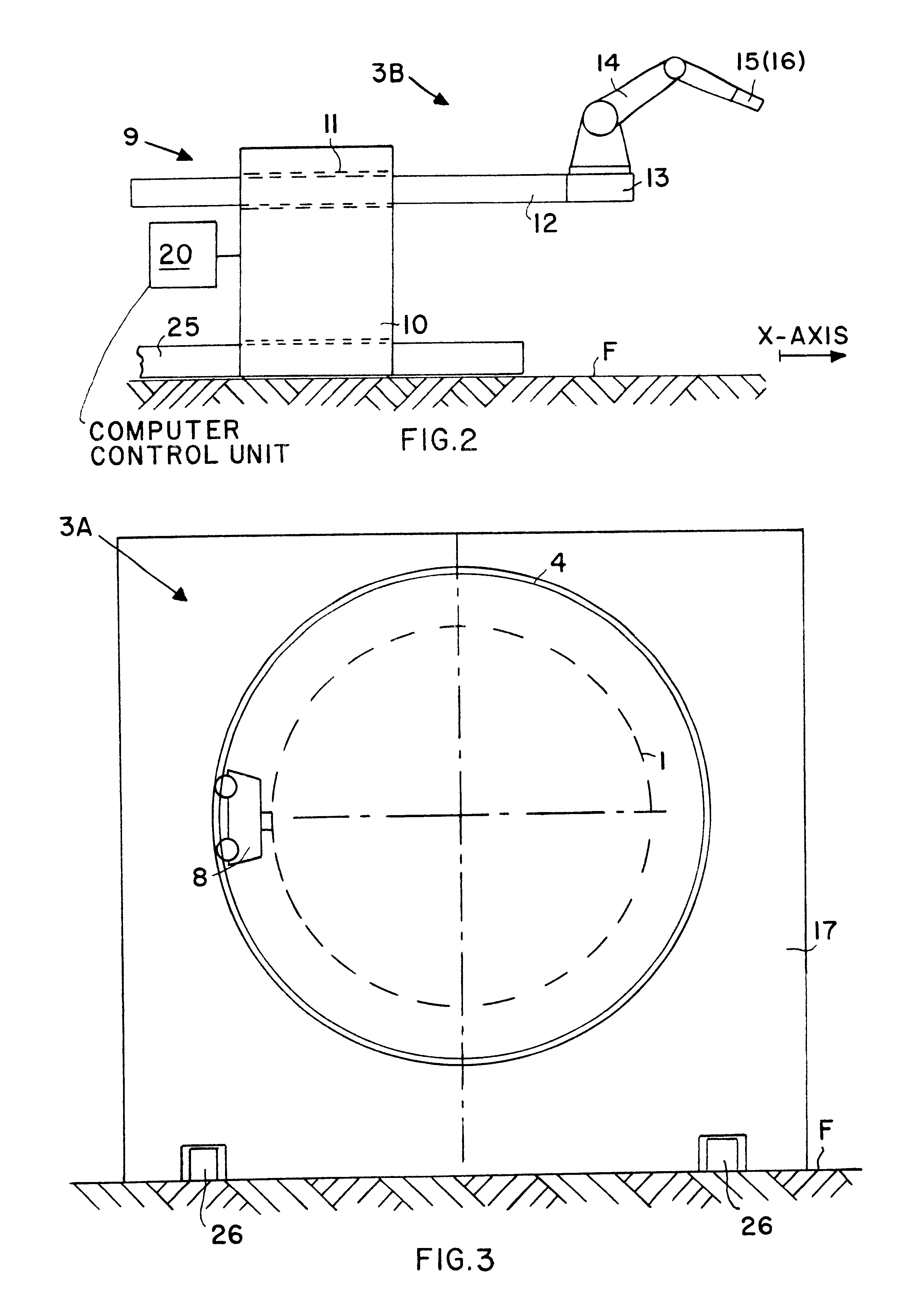
FIG. 1 shows two aircraft fuselage sections 1A and 1B as respective parts of an aircraft fuselage 1. The two fuselage sections 1A and 1B are to be joined to each other typically along a transverse or circumferential seam or joint 2A, where the joining is carried out by a great number of rivets respectively secured in corresponding rivet holes. Any known type of rivet or rivet-like fastener can be fastened along the seam using the inventive apparatus as will now be described. Also, instead of the riveting device forming a riveted joint, the present apparatus could include any other type of joining device such as a welding device or an adhesive bonding device to form respective different types of joints. The present preferred embodiment described herein uses a riveting device to form riveted joints. An automatic riveting apparatus is advantageously used for fabricating the riveted joints during the assembly of the aircraft fuselage 1, because only an automatic method and apparatus for...


PUM

PropertyMeasurementUnit
surface areaaaaaaaaaaa
perimeteraaaaaaaaaa
areaaaaaaaaaaa

Abstract

An apparatus for riveting shell components to form a barrel-shaped structure such as an aircraft fuselage includes an outer part and an inner part that operate coordinated with each other under computer control. The outer apparatus part includes a riveting machine system movably carried on an annular machine guide that is supported on a stand that is movable in a length-wise X-direction. The inner apparatus part includes a multi-axis riveting robot mounted on a mounting frame that is movable along the X-direction. Instead of moving the inner and outer apparatus parts in the X-direction, it is alternatively possible to move the fuselage while keeping the apparatus parts stationary. A computer control unit provides control signals to achieve a coordinated and concurrent positioning of the inner and outer apparatus parts, and to carry out a coordinated sequence of riveting steps. Rivets can be automatically fastened even at difficult to access locations, while avoiding structural obstacles inside the aircraft fuselage. The apparatus parts are supported independently of the fuselage on the floor of the assembly hall.

Description

PRIORITY CLAIMThis application is partly based on and claims the priority under 35 U.S.C. .sctn.119 of German Patent Application 198 34 702.2, filed on Jul. 31, 1998, through prior U.S. application Ser. No. 09 / 366,036, filed on Aug. 2, 1999. The entire disclosures of the above identified German Patent Application and prior U.S. Application are incorporated herein by reference.The invention relates to a riveting apparatus for riveting large surface area components having a curved contour to fabricate a barrel-shaped structure such as an aircraft fuselage.BACKGROUND INFORMATIONAutomatic and semi-automatic robotic riveting apparatus are known for connecting large surface area components using rivets. Such known apparatus are suitable for the fabrication of aircraft fuselage shells and other barrel-shaped or cylindrical structures that are fabricated from a plurality of individual curved components having large surface areas. For example, German Patent 35 35 761 and corresponding U.S. P...

Claims


Application Information

Patent Timeline
Patent Type & Authority Patents(United States)
IPC IPC(8): B21J15/00B21J15/10
CPCB21J15/10B21J15/142Y10T29/53065Y10T29/49956Y10T29/5377
Inventor STOEWER, UDOKOEHLER, BERNDKOSUCH, NORBERT
Owner AIRBUS OPERATIONS GMBH
Why Eureka
Try Eureka