Algorithmic compensation system and method therefor for a touch sensor panel

a technology of touch sensor and compensation system, which is applied in the direction of mechanical pattern conversion, static indicating device, instruments, etc., can solve the problems of system employing such substrates, non-linear variation, and non-uniform current density at various portions of substrates

Inactive Publication Date: 2003-01-14
ELO TOUCH SOLUTIONS INC
View PDF60 Cites 149 Cited by
  • Summary
  • Abstract
  • Description
  • Claims
  • Application Information

AI Technical Summary

Benefits of technology

It is a still further object of the invention to provide a position determining system, comprising a medium, having a surface, transmitting physical effects from one portion to another portion; a plurality of spaced detectors for sensing transmitted physical effects in said medium and each producing a detector output; and a memory for storing a plurality of values of information, corresponding to a mapping relationship of said detector outputs at a plurality of determined positions, with respect to said surface, of a physical effect applied to said medium.
It is another object according to the present invention to provide an apparatus for mapping a plurality of detector outputs to coordinate positions, comprising a medium, conducting a physical effect; at least three detectors, at different positions on said medium, each detecting a conducted portion of said physical effect; and a memory for storing information relating to a mapping of a locali

Problems solved by technology

A touchscreen system may be considered to have two classes of error, (i) those resulting from the design and implementation of the coordinate transformation method (systematic error), and (ii) those resulting from random unit to unit errors within a given class of sensors (manufacturing variance).
A particular additional source of errors in systems employing such substrates is the non-linear variation in sensed probe injection current inherent in the configuration of a generally rectangular substrate with electrodes at the corners.
This results in a non-uniform current density at various portions of the substrate, especially near the electrodes.
Because of the gross non-linearities, it is generally considered undesirable to attempt to perform a piecewise linear compensation, i.e., directly compensate for repositionable electrode position based on a lookup table calibration procedure.
The nature of these methods often results in a significant current drain on the system and the multiplicity of electrodes and/or resistance patterns leads to a high sensor cost.
Further, the management of the corrective methods, e.g. excitation switching, sensing plane selection, electrode selection, etc., mandates an interactive control mechanism that adds to the system cost.
The principal drawback to this technology is its current drain.
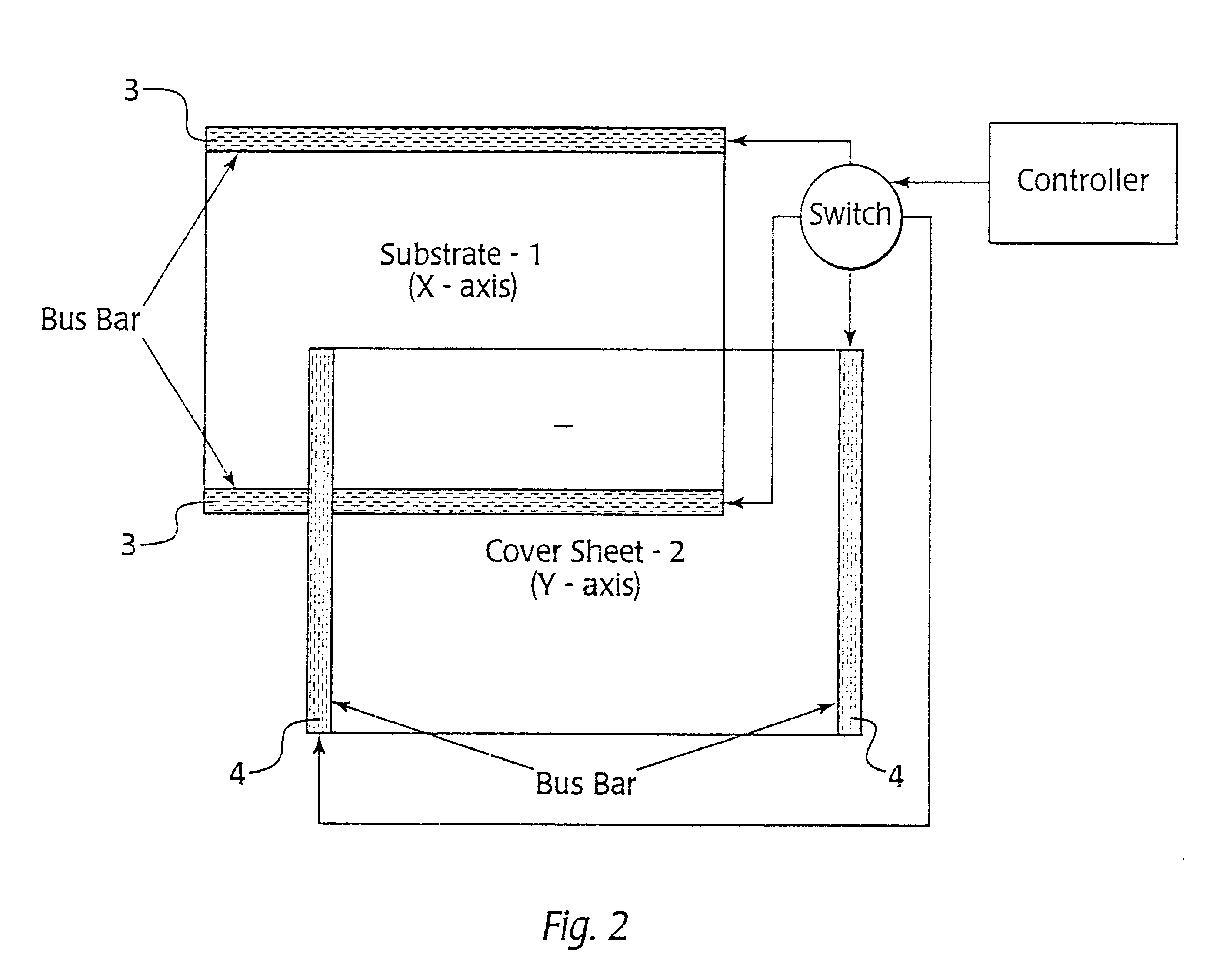
Further, in those cases where the cover sheet is employed for the second excitation plane, any coversheet damage will result in positional location errors.
However, it is a high current drain system, and requires a large number of interconnections.
F

Method used


Image

  • Algorithmic compensation system and method therefor for a touch sensor panel
  • Algorithmic compensation system and method therefor for a touch sensor panel
  • Algorithmic compensation system and method therefor for a touch sensor panel

Examples


example 2

A conductive surface substrate 110 is provided essentially as in Example 1. However, as shown in FIG. 6, no microcontroller is provided in conjunction with the sensor system. Instead, an analog data acquisition system 200 with an input multiplexer and serial interface is provided which sequentially polls the inputs and transmits the data in serial format through a serial interface driver 202 to a host processor 201, which evaluates the mapping algorithm from the raw data. Upon startup, the host processor 201 reads the contents of a coefficient storage nonvolatile memory 123, through the serial interface driver. After the stored data is transferred, the system then transmits the digitized data from the analog data acquisition system 200.

example 3

The system according to the present invention is also applicable to capacitive touch position sensors. In this case, a constant current RMS AC signal is selectively injected through one of the fixed electrodes on the conductive surface, e.g., 200 .mu.A sinusoidal RMS. The repositionable electrode includes a dielectric barrier material with an impedance to a reference, so that proximity to the conductive barrier contact attenuates the signal at that point, resulting in a variable current loss. The current at each of the other fixed electrodes is measured. The input current is therefore equal to the currents measured at the other corners plus the parasitic losses of the system. When a dielectric touches the surface, a further loss occurs, the position of which may be measured as a function of the three sensed corners.

In another capacitive touch system, a constant current RMS AC signal is selectively transmitted from a touch position to a conductive surface. AC currents at the pluralit...

example 4

As shown in FIG. 11, a substrate 220 is provided having a plurality of force detectors 221. The outputs of the detectors 221 are multiplexed through multiplexer 222 and digitized by analog to digital converter 223. A microcontroller 224 receives the output of the analog to digital converter 223, and determines a position of touch based on a mapping algorithm stored in ROM 226, based on a series of coefficients stored in nonvolatile memory 227 which are derived from an initial measurement procedure and least mean square fitting. The force against the substrate is divided between the detectors 221, with a nonlinear relationship between the touch position and the response of any detector 221. The output response of each detector 221 may also be nonlinear. Further, compliance of the substrate 220 may also produce nonlinearities. The algorithm corrects for the relationship of force location and detector 221 output to produce a corrected results.


PUM


Abstract

A general method is described for producing an inexpensive touchscreen system that provides accurate positional information and compensates for manufacturing variations without complicated sensor arrangements. Utilizing a set of sensed signals that are unique to each location on the touchscreen sensor, equations for X and Y are derived via curve fitting methods. The coefficients of the equations are stored with the sensor. During touchscreen operation the coefficients are used to calculate X and Y to the desired accuracy directly and independently.

Description

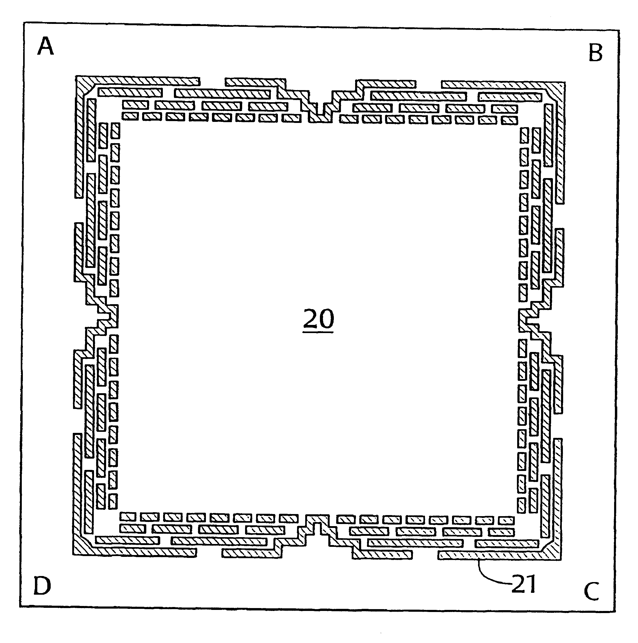
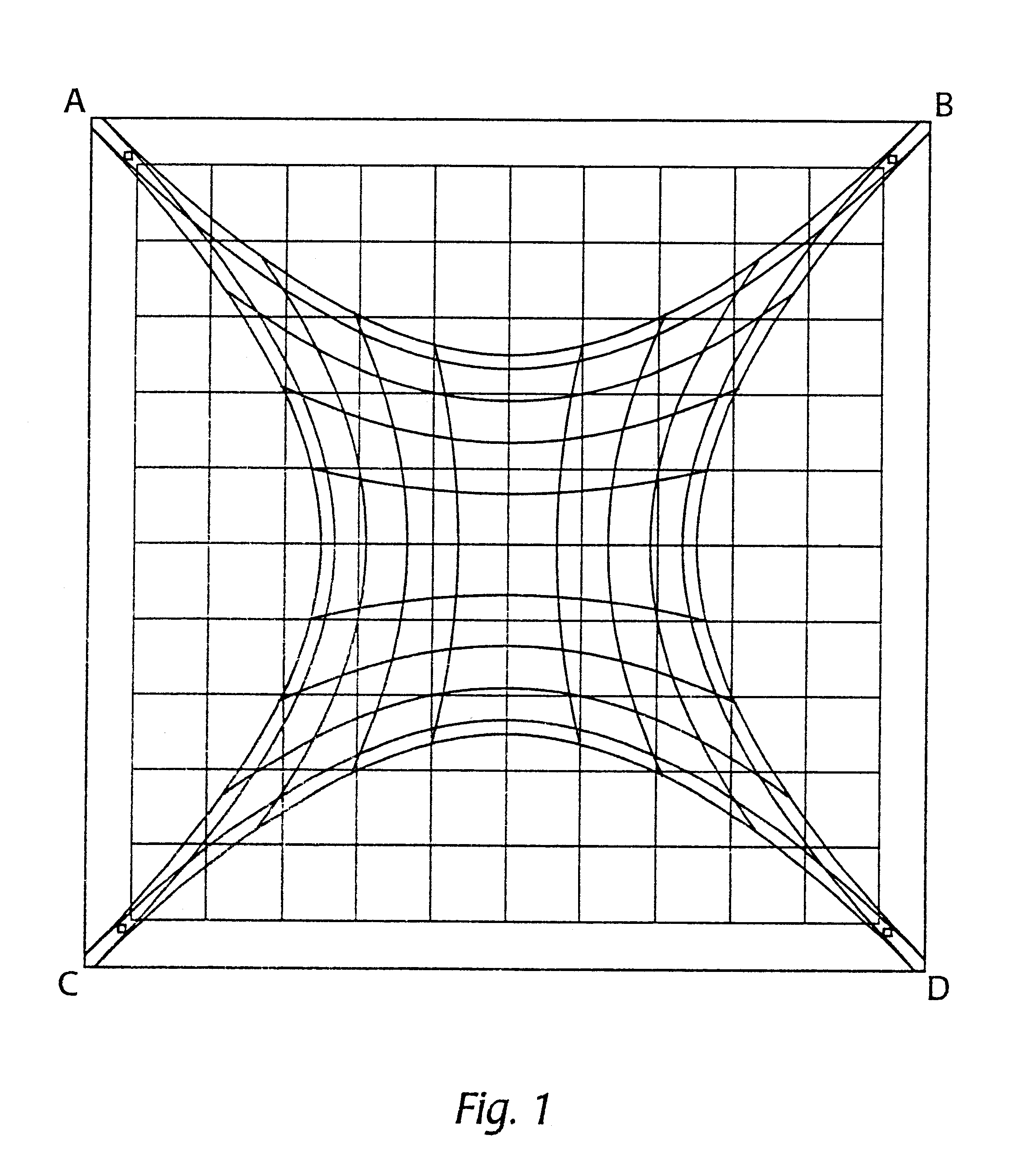
The present invention relates to a method and system for deriving or employing a mapping relation for determining coordinate positions of a physical effect on a substrate from a plurality of detectors. More particularly, the invention relates to a touchscreen system with a plurality of corner detectors, applying the mapping relation to accurately determine a coordinate position of a touch from the detector outputs, regardless of configuration and possible manufacturing variations.The functionality of a touchscreen system (typically including a touchscreen and an electronic controller) requires that there exist a relationship between the physical location of a touch, e.g. by a person's finger, and some coordinate schema. In general, the coordinate system of choice is a two-dimensional Cartesian system with orthogonal horizontal (X) and vertical (Y) axes. The system accuracy is defined as the error between the physical location of the touch and the location reported by the touchscreen...

Claims


Application Information

Patent Timeline
IPC IPC(8): G06F3/033G01B7/00G06F3/041G06F3/045G08C21/00
CPCG06F3/045G08C21/00
Inventor BABB, JOE HENRYWILSON, GEOFFREY D.
Owner ELO TOUCH SOLUTIONS INC
Why Eureka
Try Eureka