
Inductor core-coil assembly and manufacturing thereof

a core-coil and assembly technology, applied in the direction of transformer/inductance coil/winding/connection inductance with magnetic core, etc., can solve the problem of difficult automatic process, and achieve the effect of improving the magnetic performance of the gapped core and improving the production yield of the core-coil assembly

Inactive Publication Date: 2003-01-28
SHT CO LTD
View PDF13 Cites 64 Cited by
  • Summary
  • Abstract
  • Description
  • Claims
  • Application Information

AI Technical Summary

Benefits of technology

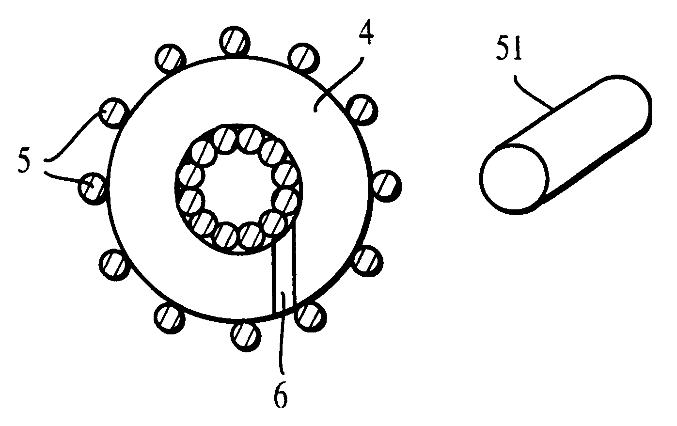
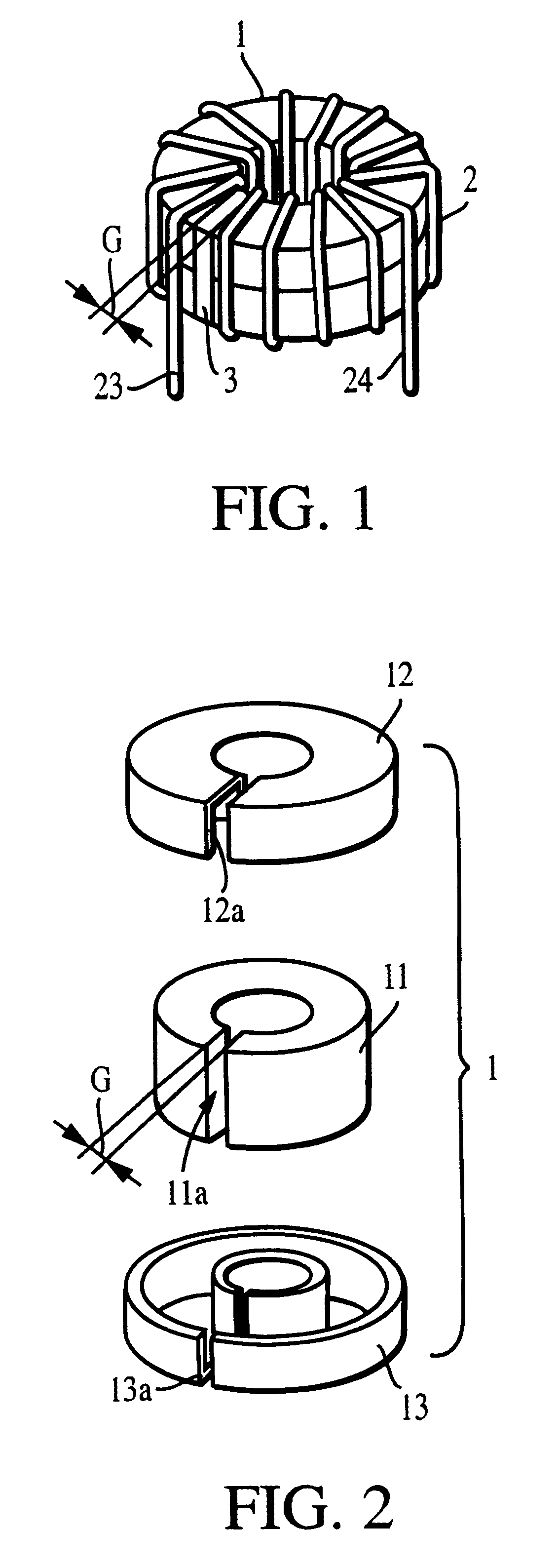
In accordance with the invention, there is provided a core-coil assembly and manufacturing thereof. A magnetic core has at least one physical gap and an insulated core assembly is formed by coating the gapped magnetic core with an electrical insulator or covering it with an insulating box having a physical gap whose dimension is close to that of the magnetic core gap. A copper wire passes through the gap of the core or the core assembly to be wound on the core or the core assembly. The copper-wire winding is also performed by rotating the core or the core assembly around the tangential direction of the circumference of the core or the core assembly. To improve magnetic performance of a gapped core, a non-conventional gap is introduced whose direction is off the radial direction of a toroidally wound core. The magnetically improved core with a non-conventional gap can be housed in a conventional core box with no gap and a copper winding may be applied on it to use it as in inductor. The copper winding part, on the other hand, can be prefabricated separately and a gapped core or core assembly is then inserted into the prefabricated coil through the gap. The gap section of the core or the core assembly may be filled with a magnetic or non-magnetic spacer during or after coil-winding operation. The core-coil assembling method of the present invention is much simpler than the existing method and thus is fully or semi-automated, improving core-coil assembly production yield with consistent performance.

Problems solved by technology

However, due to the nature of this operation, such equipment requires a wire handling mechanism akin to that of a sewing machine which uses flexible threads.
When the wire size is thick, such automated process becomes difficult and manual copper winding is a standard practice.

Method used


Image

  • Inductor core-coil assembly and manufacturing thereof
  • Inductor core-coil assembly and manufacturing thereof
  • Inductor core-coil assembly and manufacturing thereof

Examples


Embodiment Construction

1. Sample Preparation

Magnetic cores were prepared by consolidating magnetic powder or winding a magnetic-metal ribbon onto a mandrel. When necessary, the cores were then heat-treated to achieve required magnetic properties. The cores were cut by an abrasive cutting tool or by a water jet to introduce a gap. Copper windings were applied on each core for magnetic measurements.

2. Magnetic Measurements

The inductance of a core-coil assembly was measured by a commercially available inductance bridge and the core's magnetic core loss was measured by the method described in the IEEE Standard 393-1991.

3. Magnetic Properties of Core-Coil Assemblies

Core-coils assemblies in accordance with the present invention were evaluated. FIG. 19 compares the inductance measured at 1 kHz as a function of bias current for two types of core-coil assemblies, one with the configuration of FIG. 9 which resulted in curve A and the other corresponding to FIG. 1 which resulted in curve B. The size of the cores for...


PUM


Abstract

Disclosed are a gapped magnetic core which may be coated or uncoated with an insulating layer or housed in an insulting box having a physical gap whose dimension is close to that of the gapped magnetic core and automated or semi-automated methods of applying copper wire on the gapped core or the core assembly and filling the gap with a spacer in the core or core assembly. The disclosed processes allow various combinations of core and spacer materials and gap configurations, resulting in a wide variety of core-coil assemblies which are useful as inductive components in electric and electronic circuits. Also disclosed is a core-coil assembly wherein a magnetic core with a gap directed off the conventional radial direction of a toroidally-wound core.

Description

This invention relates to inductor core-coil assembly for use as magnetic components in electric and electronic circuits such as converters, inverters, noise filters, resonant circuits, and the like.BACKGROUND OF INVENTIONCurrently two types of magnetic cores are widely used in the inductive components in electric and electronic circuits such as AC-to-DC and DC-to-DC converters, inverters, filters for electronic noises, electronic resonant circuits and the like. One kind is a toroidally-shaped core with no physical gap and the other has at least one gap. In both cases, copper winding(s) must be applied on the core to form a magnetic inductor. When the required copper wire size is thin, the copper winding can be automated and equipment for such operation is available. However, due to the nature of this operation, such equipment requires a wire handling mechanism akin to that of a sewing machine which uses flexible threads. When the wire size is thick, such automated process becomes d...

Claims


Application Information

Patent Timeline
IPC IPC(8): H01F17/06H01F41/08H01F41/06H01F37/00
CPCH01F41/08H01F17/062H01F27/32B82Y30/00
Inventor YOSHIMORI, HITOSHIHASEGAWA, RYUSUKE
Owner SHT CO LTD
Learn More