Method and apparatus to estimate location and orientation of objects during magnetic resonance imaging

a technology of magnetic resonance imaging and location and orientation, applied in the field of method and apparatus to estimate the location and orientation of objects during magnetic resonance imaging, can solve the problems of limiting the application of sterotaxis and frameless techniques to the use of rigid devices, and affecting the accuracy of orientation estimation

Inactive Publication Date: 2003-02-04
ROBIN MEDICAL
View PDF5 Cites 307 Cited by
  • Summary
  • Abstract
  • Description
  • Claims
  • Application Information

AI Technical Summary

Benefits of technology

The present invention has significant advantages over existing methodologies. Compared with sterotaxis, either the frame or frameless techniques, the new methodology enables the use of devices like catheters or surgical instrumentation without the need for direct line of sight with the device. Unlike the remote electromagnetic localization methodology of Acker et al the present invention is based on measurement of voltages induced by a set of time-varying electromagnetic gradient fields in a set of coils (Faraday Law), rather than the need to use homogenous and gradient fields which induce voltages in a set of miniature conductors carrying electrical current (Hall effect). Thus, the present invention is totally passive, it does not require any excitation of the sensors, nor the use of dedicated magnetic fields, and the requirement for time-variable magnetic fields is satisfied with virtually any MRI scanning protocol which is in routing clinical use. The methods disclosed by Pfeiler et al and Dumouline et al require the use of two sensors to measure orientations and thus have limited accuracy of orientation estimation, while the present invention uses a sensor which provides simultaneously accurate orientation and location tracking. Unlike existing optical tracking systems, there is no limitation on the number of sensors being used, and there is no need to maintain a line of sight between the sensor and the tracking apparatus. All other tracking methodologies are based on their own reference system, and should be aligned with the MRI coordinate system by a time-consuming registration procedure. The disclosed tracking methodology does not require registration since it uses the same set of gradient coils which are used by the MRI scanner for spatial encoding of the images.

Problems solved by technology

Yet both the sterotaxis and the frameless techniques are typically limited to the use of rigid devices like needles or biopsy forceps since their adequate operation requires either mechanical attachments or line of sight between the light sources and the sensors.
As with the previous methodology, the application of the technology to MRI is problematic due to the simultaneous use of RF signals by the MR scanning.
Potential difficulties are the heating of the receiving antenna in the device by the high amplitude excitation RF transmissions of the MRI scanner and artifacts in the MR image.
This method cannot directly determine the orientation of the device, and may be subject to similar difficulties as the previous technology, including heating of the coil.
The absence of beam-hardening artifacts from bone allows complex approaches to anatomic regions that may be difficult or impossible with other imaging techniques such as conventional CT.

Method used


Image

  • Method and apparatus to estimate location and orientation of objects during magnetic resonance imaging
  • Method and apparatus to estimate location and orientation of objects during magnetic resonance imaging
  • Method and apparatus to estimate location and orientation of objects during magnetic resonance imaging

Examples


Embodiment Construction

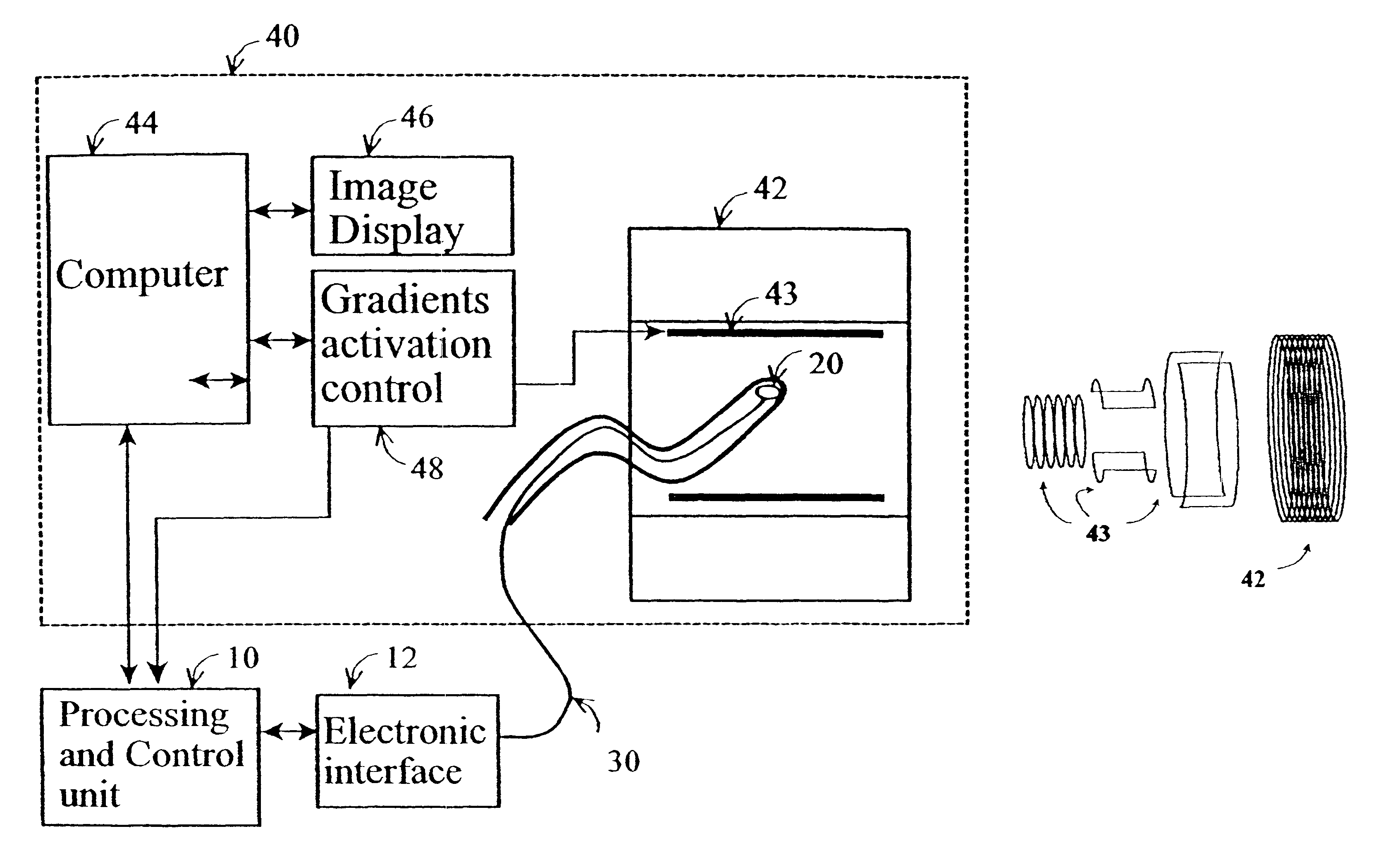
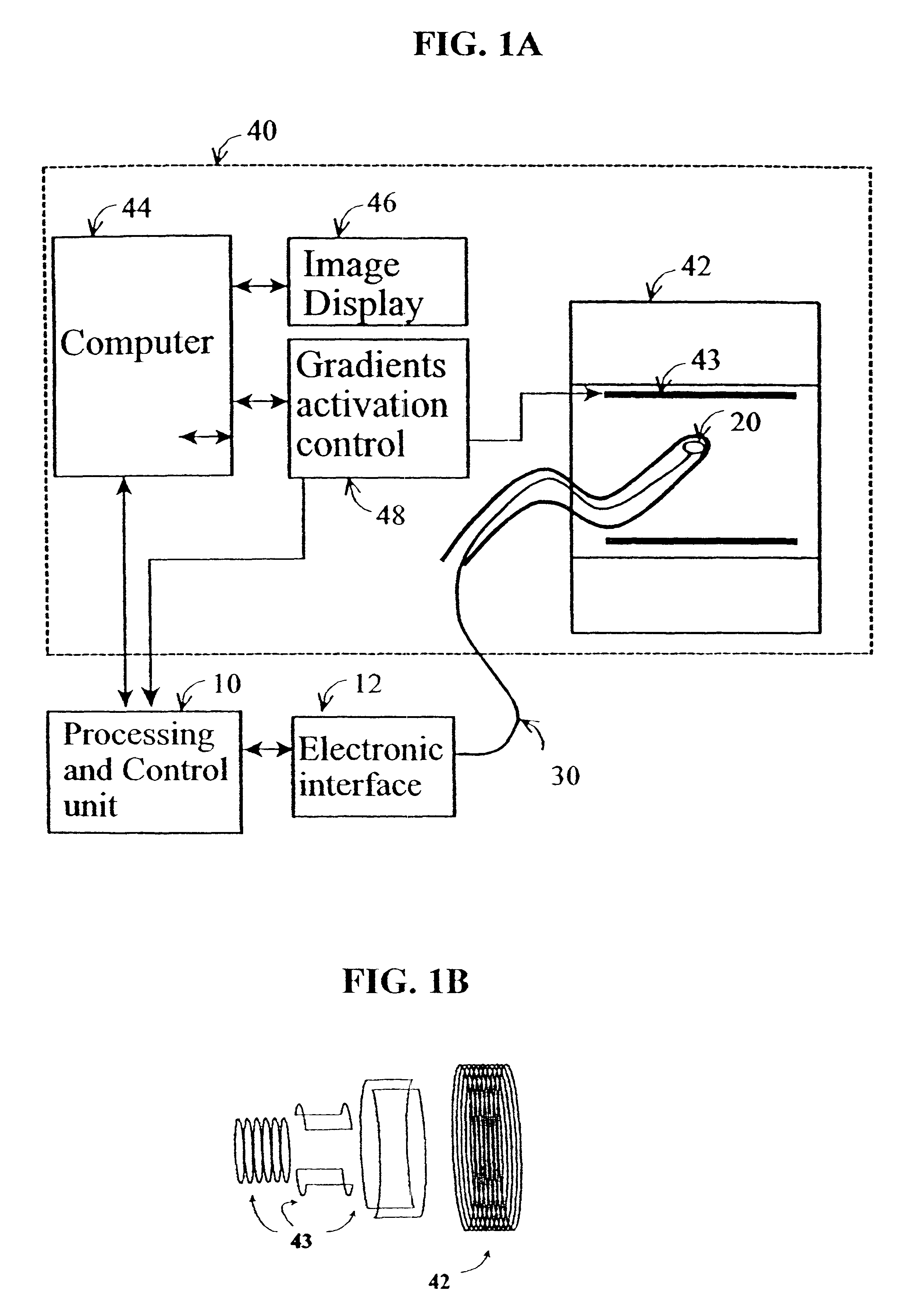
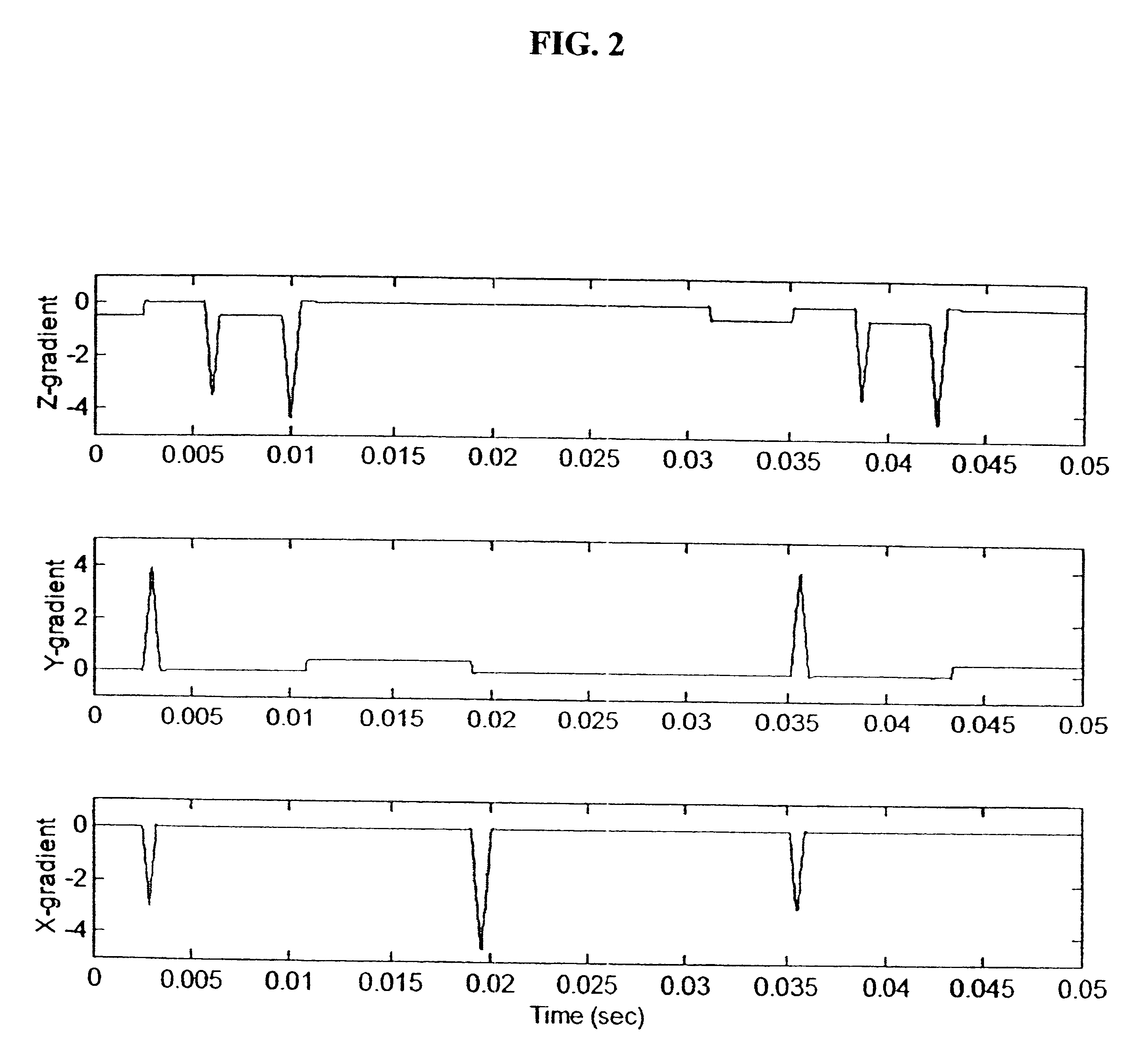
Referring now to FIG. 1, a typical MRI system (40) has several modules which are specifically relevant to the current invention: the three gradient coils (43), the gradient coils control unit (48), and the image display (46). The exact implementation of the invented methodology depends on the MRI mode of imaging, and the following presentation relates, as a typical example, to a standard MRI spin-echo imaging mode. During the spin-echo protocol, repeated generation of magnetic fields by the 3 gradient coils provide the spatial encoding of the received MR echo and enable the reconstruction of the image. A sample sequence is given in FIG. 2 (recorded from a Signa MRI system, General Electric, USA). For this sequence the system activates the Z-gradient coil for "slice selection", simultaneously the X and Y gradient coils for "phase encoding" and the X gradient coil for the "read out" phase.

The gradient control unit (48) provides the processing unit (10) with real-time presentation of t...


PUM


Abstract

Method and apparatus for determining the instantaneous location, the orientation of an object moving through a three-dimensional space by applying to the object a coil assembly including a plurality of sensor coils (20) having axes of known orientation with respect to each other including components in the three orthogonal planes; generating a time-varying, three-dimensional magnetic field gradient having known instantaneous values of magnitude and direction; applying the magnetic field gradient to the space, and object moving therethrough to induce electrical potentials in the sensor coils; measuring the instantaneous values of the induced electrical potentials generated in the sensor coils; processing the measured instantaneous values generated in the sensor coils together with the known magnitude, direction of the generated magnetic field gradient, the known relative orientation of the sensor coils in the coil assembly to compute the instantaneous location, orientation of the object within the space.

Description

FIELD OF THE INVENTIONThe invention relates to methodology and apparatus to determine the location and orientation of an object, for example a medical device, located inside or outside a body, while the body is being scanned by magnetic resonance imaging (MRI). More specifically, the invention enables estimation of the location and orientation of various devices(e.g. catheters, surgery instruments, biopsy needles, etc.) by measuring voltages induced by time-variable magnetic fields in a set of miniature coils. Such time-variable magnetic fields are generated by an MRI scanner during its normal operation.BACKGROUND OF THE INVENTIONMinimally invasive procedures: Minimally-invasive diagnostic or interventional procedures require either direct visual viewing or indirect imaging of the field of operation and determination of the location and orientation of the operational device. For example, laparoscopic interventions are controlled by direct viewing of the operational field with rigid ...

Claims


Application Information

Patent Timeline
Patent Type & Authority Patents(United States)
IPC IPC(8): A61B5/06
CPCA61B5/06
Inventor NEVO, EREZ
Owner ROBIN MEDICAL
Why Eureka
Try Eureka