Large surface area x-ray tube shield structure

a shield structure and large surface area technology, applied in the field of x-ray tubes, can solve the problems of shortening the operational life affecting the quality of the x-ray image, and high temperature of the x-ray tube structur

Inactive Publication Date: 2003-02-11
VAREX IMAGING CORP
View PDF13 Cites 36 Cited by
  • Summary
  • Abstract
  • Description
  • Claims
  • Application Information

AI Technical Summary

Problems solved by technology

In this way, the rebounding electrons are prevented from reimpacting the target anode and producing "off-focus" x-rays, which can negatively affect the quality of the x-ray image.
While such a shield structure may prevent rebounding electrons from re-striking the anode target, its use can result in additional problems that can ultimately damage the x-ray tube device, and shorten its operational life.
Due to the high level of kinetic energy of the electrons, the thermal energy produced by these impacts is significant and typically results in very high temperatures in the x-ray tube structures.
These 
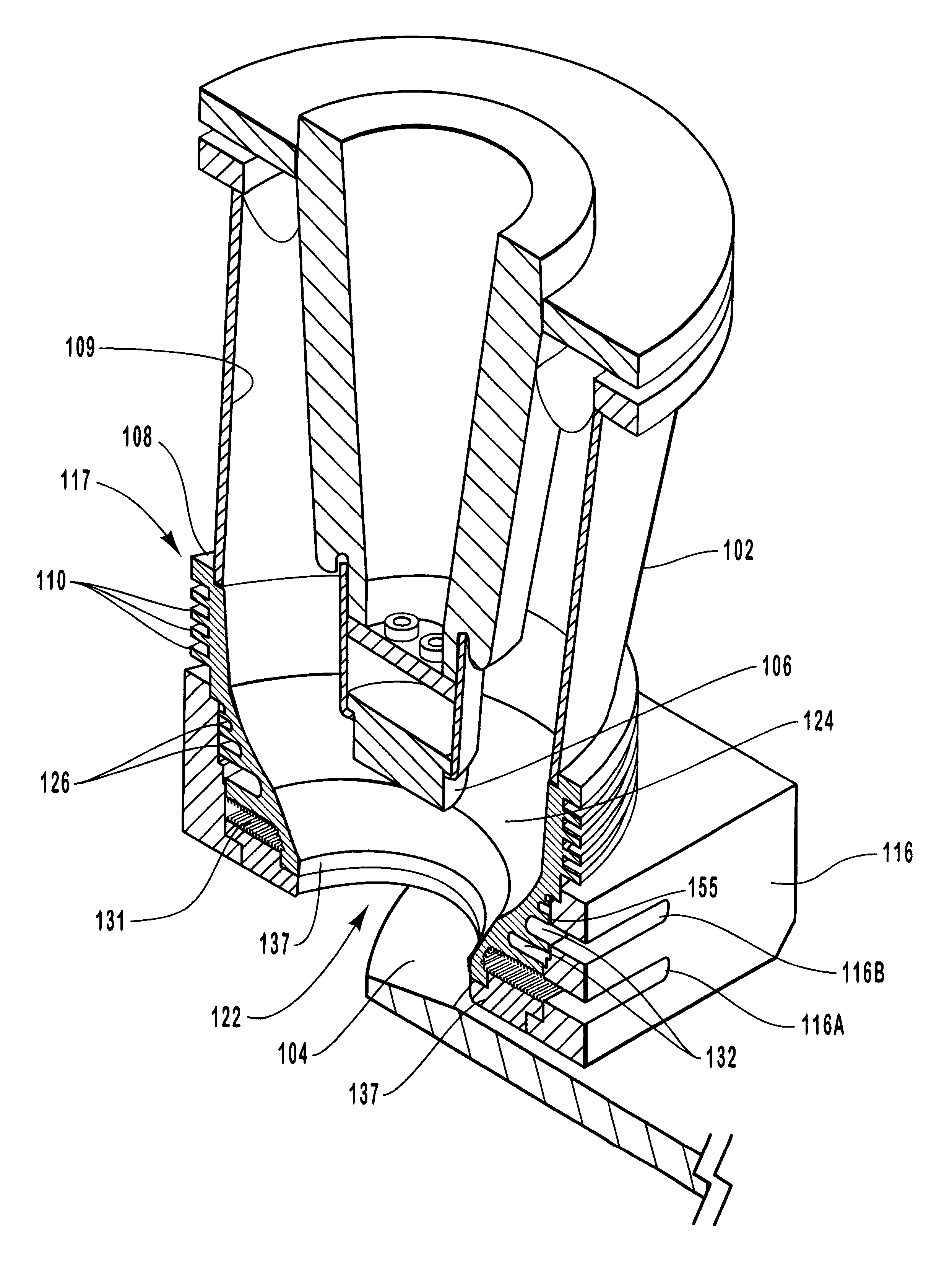
thigh temperatures, in combination with the high temperatures also being generated at the target anode, cause thermal stresses in the structures (including the cathode cylinder and the shield) and structure joints that can, especially over time, lead to various structural failures in the x-ray tube assembly.
Moreover, because the rebounding electrons impact some portions of the cathode cylinder and shield structure with relatively greater frequency than other portions the heat produced by the rebounding electrons is not evenly distributed.
Accordingly, the different heat regions are collectively characterized by varying rates of thermal expansion, resulting in mechanical stresses that can also damage the x-ray tube device, especially over numerous operating cycles.
However, non-uniform expansion produced by high temperature differentials induces destructive mechanical stresses and strains that can ultimately cause a mechanical failure in the part.
Moreover, these stresses are especially damaging to joints between attached components.
However, previously available x-ray tube cooling systems have not been entirely satisfactory in providing effective and efficient cooling--especially in the regions of the shield structure and cathode cylinder.
Often however, this approach is

Method used


Image

  • Large surface area x-ray tube shield structure
  • Large surface area x-ray tube shield structure
  • Large surface area x-ray tube shield structure

Examples


Embodiment Construction

Reference will now be made to the figures, wherein like structures will be provided with like reference designations. It is to be understood that the drawings are diagrammatic and schematic representations of presently preferred embodiments of the present invention and are not limiting of the present invention, nor are they necessarily drawn to scale.

Referring first to FIGS. 1 and 2 together, the relevant portions of an x-ray tube device are depicted generally at 100. An x-ray tube, designated generally at 101, is formed generally with an evacuated envelope housing that is typically referred to as a "can" 107. The evacuated envelope, or can, 107 is disposed within a housing 112. Disposed within can 107 is an electron source in the form of a cathode head 106, filament (not shown) and associated electronics (not shown), that is disposed within a cathode cylinder 102. Adjacent to the cathode 106, and attached to the end of cathode cylinder 102, is a electron collection device, sometime...


PUM


Abstract

An improved x-ray tube cooling system is disclosed. The system utilizes a shield structure that is connected between a cathode cylinder and an x-ray tube housing and is disposed between the electron source and the target anode. The shield includes a plurality of cooling fins to improve overall cooling of the x-ray tube and the shield so as to extend the life of the x-ray tube and related components. When immersed in a reservoir of coolant fluid, the fins facilitate improved heat transfer by convection from the shield to the to the coolant fluid. The cooling effect achieved with the cooling fins is further augmented by a convective cooling system provided by a plurality of fluid passageways formed within the shield, which are used to provide a fluid path to the coolant. In particular, a cooling unit takes fluid from the reservoir, cools the fluid, then circulates the cooled fluid through the fluid passageways. One or more depressions of "V" shaped cross section defined on the surfaces of the fluid passageways serve to facilitate nucleate boiling of the coolant in the passageway, and thereby materially increase the heat flux through the passageway to the coolant. Additionally, one or more extended surfaces disposed on the surfaces of the fluid passageways also facilitate a relative increase in the rate of heat transfer from the shield structure to the coolant. After flowing through the fluid passageway, the coolant is then discharged from the fluid passageways and directed over the cooling fins. In some embodiments, the fluid passageways are oriented so as to provide a greater heat transfer rate in certain sections of the shield than in other sections. Also disclosed is an improved braze joint for connecting the shield to the x-ray tube housing.

Description

1. The Field of the InventionThe present invention relates generally to x-ray tubes. More particularly, embodiments of the present invention relate to an x-ray tube cooling system that increases the rate of heat transfer from the x-ray tube to a cooling system medium, thereby significantly reducing heat-induced stress and strain in x-ray tube structures and extending the operating life of the device.2. The Relevant TechnologyX-ray producing devices are extremely valuable tools that are used in a wide variety of applications, both industrial and medical. For example, such equipment is commonly used in areas such as diagnostic and therapeutic radiology; semiconductor manufacture and fabrication; and materials analysis and testing.While used in a number of different applications, the basic operation of x-ray devices is similar. In general, x-rays, or x-ray radiation, are produced when electrons are produced and released, accelerated, and then stopped abruptly. The typical basic x-ray t...

Claims


Application Information

Patent Timeline
IPC IPC(8): H01J35/16H01J35/00H05G1/00H05G1/04H05G1/02G21K5/02H01J35/12H05G1/06
CPCH01J35/12H01J35/16H05G1/025H05G1/04H05G1/06H01J2235/12H01J2235/1216H01J2235/125H01J2235/1283H01J2235/168H01J2235/1262
Inventor ANDREWS, GREGORY C.
Owner VAREX IMAGING CORP
Why Eureka
Try Eureka