Position sensor having compact arrangement of coils

a position sensor and compact technology, applied in the direction of coils, continuously variable inductance/transformers, transmission systems, etc., can solve the problems of reducing and affecting the overall accuracy of the position sensor

Inactive Publication Date: 2003-02-18
SINNAPTIX
View PDF124 Cites 237 Cited by
  • Summary
  • Abstract
  • Description
  • Claims
  • Application Information

AI Technical Summary

Benefits of technology

The sensor windings and the excitation windings are preferably formed on a two-layer printed circuit board since these are cheap and easy to manufacture as compared with multi-layer circuit boards. For low cost, small size and optimum EMC performance, the electronics used to generate the excitation current and to process the signals induced in the sensor windings should be mounted on the same circuit board as the sensor windings. In the systems provided to date, these connections have been made by twisted pair flying leads, which are fiddly, expensive and can be unreliable. Connections can be made using conventional PCB track routing techniques. However, the connection tracks usually result (i) in a disturbance in the sinusoidal coupling relationship between the sensor windings and the resonator; and (ii) in the sensor windings being sensitive to the magnetic field generated by the excitation coil, both of which reduce the overall accuracy of the position sensor.
One solution to this problem is simply to use multilayer printed circuit boards. However, this approach increases cost and can reduce position sensing accuracy since several printed circuit board layers require accurate registration instead of just two.
Such a transducer provides the advantage that for a given size of circuit board, the area of the loops of the first circuit can be maximised regardless of the number of turns of the second circuit.

Problems solved by technology

However, the use of a conductive screen has the disadvantages that the output signal levels are much smaller and that the signal induced in the sensor windings by the conductive screen has substantially the same phase but opposite polarity to any signal generated in the sensor windings directly from the excitation winding.
In the systems provided to date, these connections have been made by twisted pair flying leads, which are fiddly, expensive and can be unreliable.
However, the connection tracks usually result (i) in a disturbance in the sinusoidal coupling relationship between the sensor windings and the resonator; and (ii) in the sensor windings being sensitive to the magnetic field generated by the excitation coil, both of which reduce the overall accuracy of the position sensor.
However, this approach increases cost and can reduce position sensing accuracy since several printed circuit board layers require accurate registration instead of just two.

Method used


Image

  • Position sensor having compact arrangement of coils
  • Position sensor having compact arrangement of coils
  • Position sensor having compact arrangement of coils

Examples


Embodiment Construction

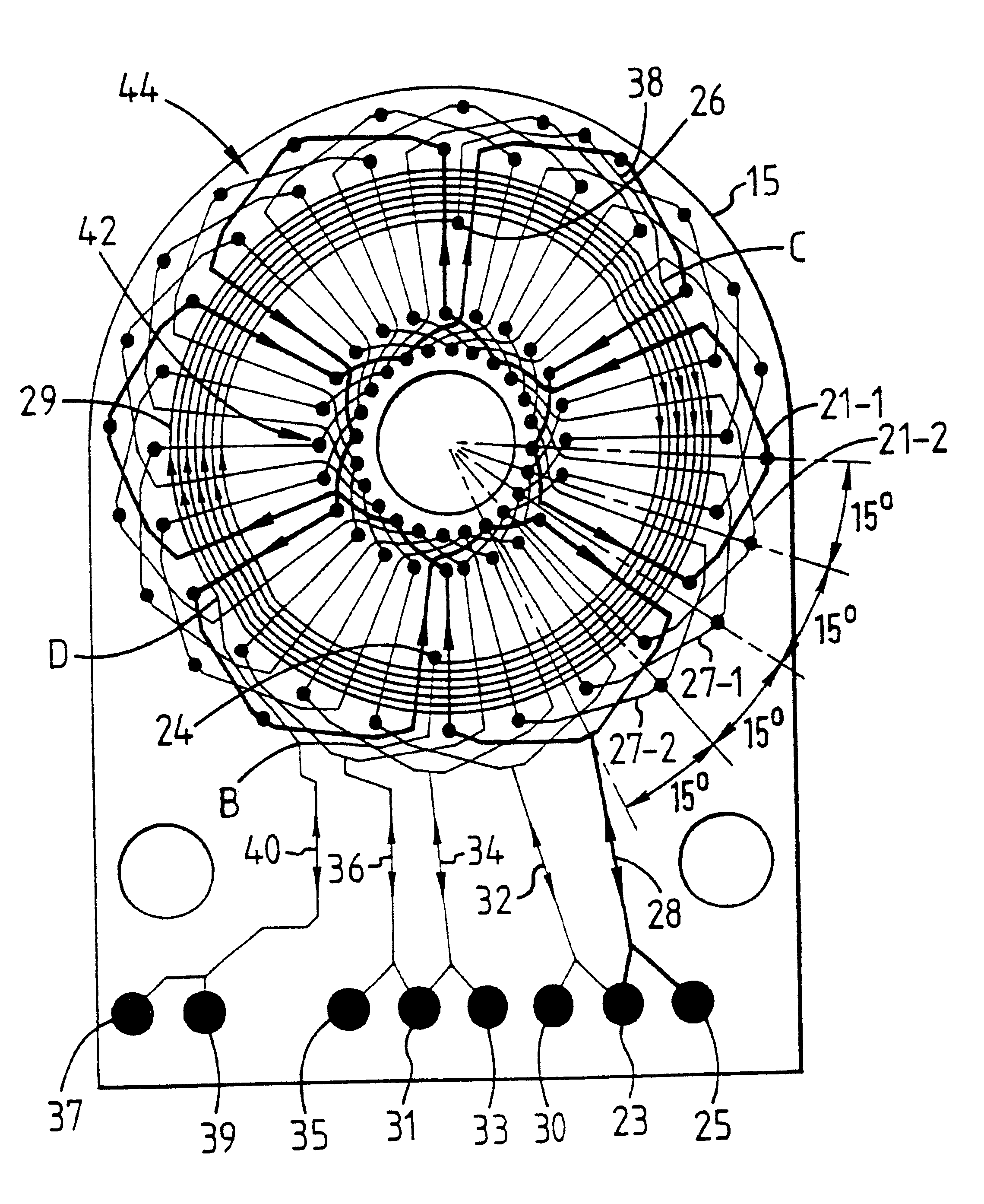
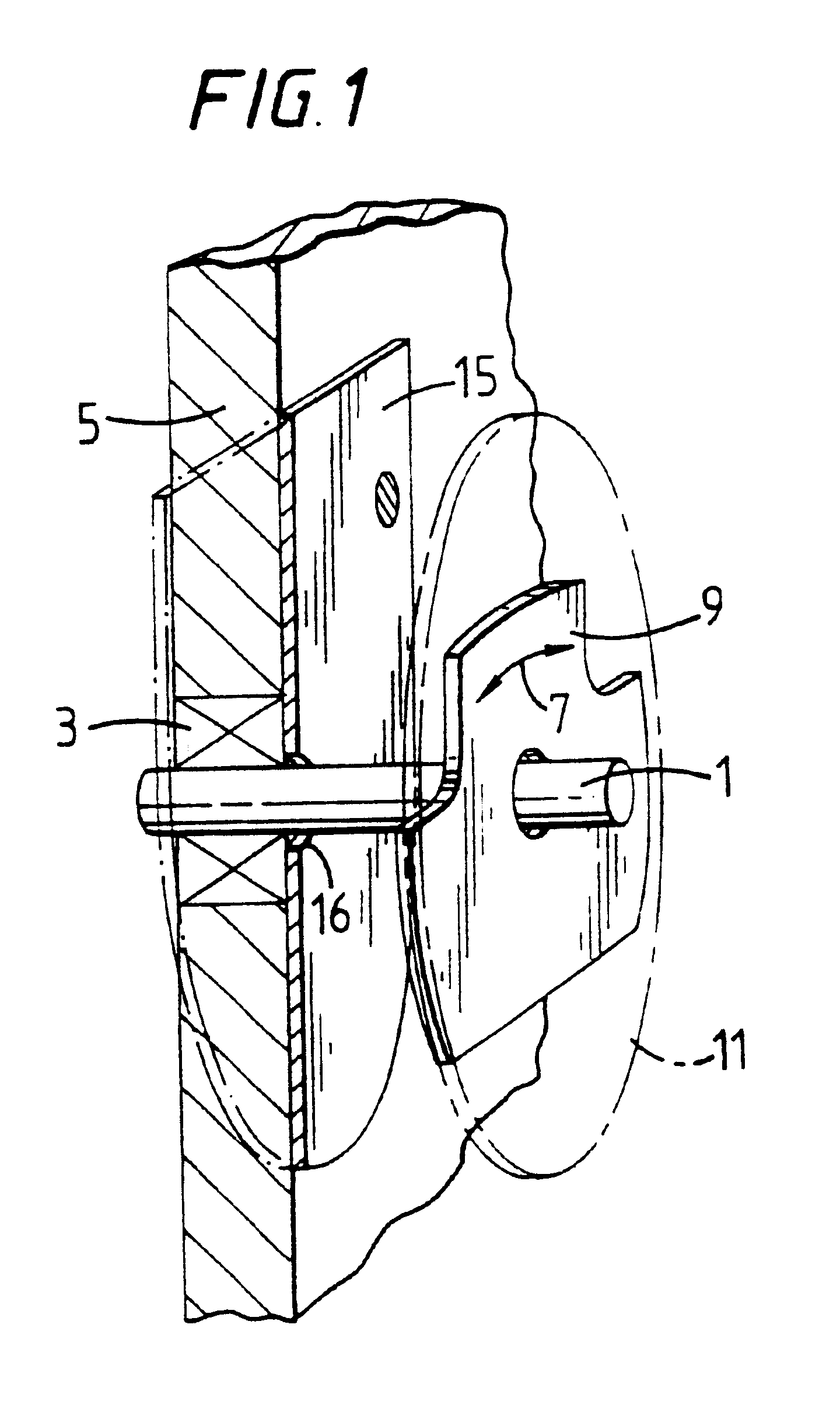
FIG. 1 schematically shows a shaft 1 which is rotatable about its axis and which passes through a bearing 3 provided in a support wall 5. A first printed circuit board 9 carrying a resonator (not shown) is mounted for rotation (as represented by arrow 7) with the shaft 1 via bushing 11 next to a second printed circuit board 15 (shown in cross-section) which carries a number of sensor windings (not shown) and an excitation winding (not shown). The second printed circuit board 15 is fixed to the support wall 5 and has a central hole 16 through which the rotatable shaft 1 passes.

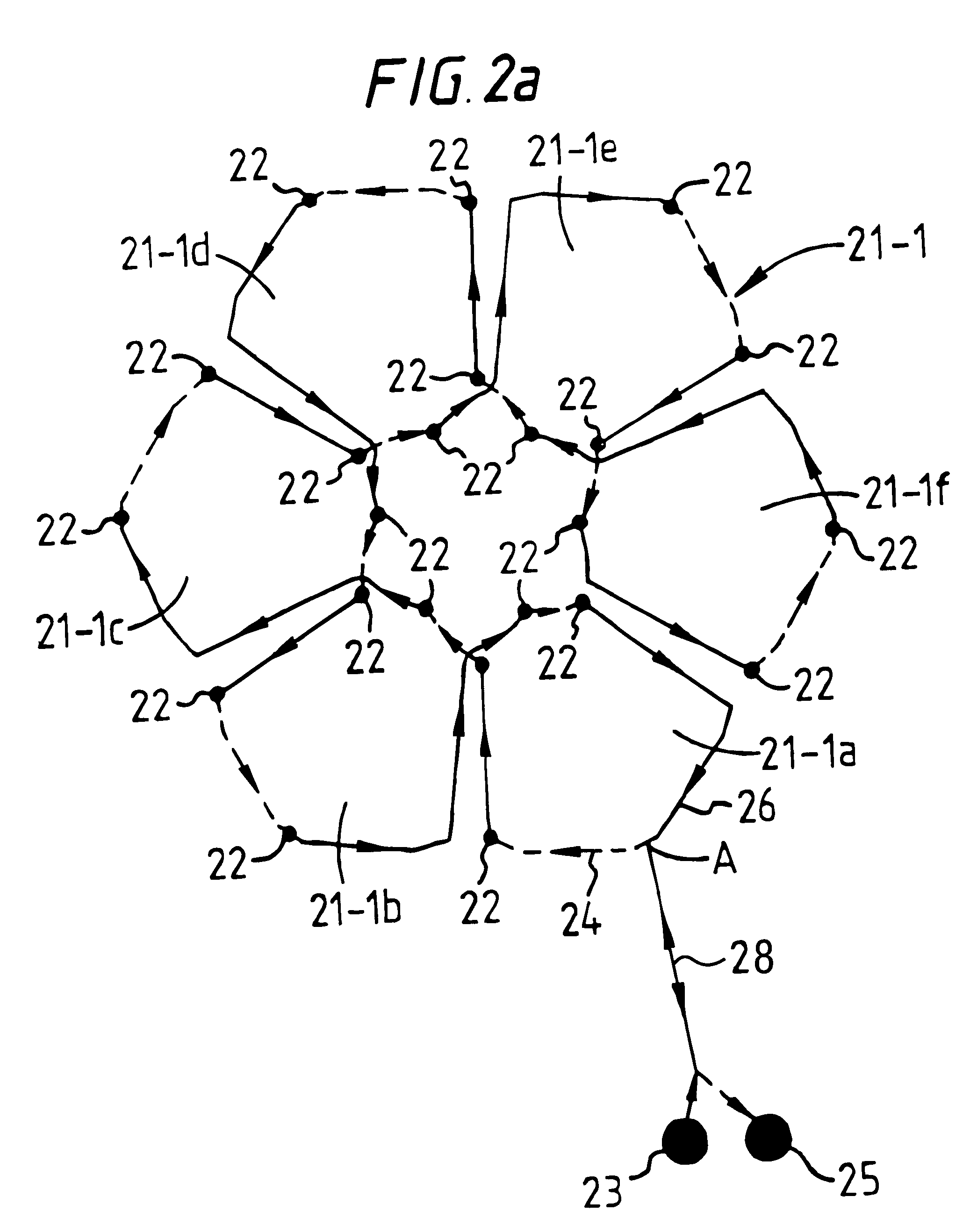
The excitation winding, sensor windings and the resonator are arranged such that when an excitation current is applied to the excitation winding, the resonator is energised which induces signals in the sensor windings, the peak amplitudes of which vary sinusoidally with the angle of rotation of the shaft. The sensor windings are connected to processing electronics (not shown) which processes the induced signals...


PUM


Abstract

A transducer is provided for use in a position sensor which senses the position of two relatively movable members. In one form, the transducer has a plurality of sensor windings having a number of loops arranged in succession and connected in series so that signals induced in adjacent loops by a common electromagnetic field oppose each other and an excitation winding having at least one loop super-imposed on but electrically isolated from the loops of the sensor windings.

Description

1. Field of the InventionThe present invention relates to an apparatus for use in a position sensor which senses the relative position between at least two relatively movable members. The invention has application in linear and rotary inductive position sensors.2. Related ArtWO95 / 31696 discloses an inductive position sensor in which one member carries an excitation winding and a number of sensor windings mounted on a sensor printed circuit board and the other member carries a resonator, also mounted on a printed circuit board. In operation, an alternating current is applied to the excitation winding which causes an alternating magnetic field to be set up in the region of the sensor printed circuit board. This field inductively couples with the resonator when it is placed in proximity to the sensor printed circuit board, to cause the resonator to resonate. This in turn generates its own spatially patterned alternating magnetic field in the vicinity of the sensor printed circuit board...

Claims


Application Information

Patent Timeline
Patent Type & Authority Patents(United States)
IPC IPC(8): G01D5/20G01B7/30G01D5/12H05K1/16G01B7/00G01D5/245
CPCG01B7/30G01D5/204H05K1/165
Inventor ELY, DAVID T. F.DAMES, ANDREW N.
Owner SINNAPTIX
Why Eureka
Try Eureka