
Measuring the concentration of a substance

a technology of concentration and measurement method, applied in the field of assay substance, can solve the problems of a large disadvantage of the apparatus, a significant portion of the total cost of the sensor, and relatively high cos

Inactive Publication Date: 2003-03-11
CANCER RES TECH LTD
View PDF10 Cites 38 Cited by
  • Summary
  • Abstract
  • Description
  • Claims
  • Application Information

AI Technical Summary

Benefits of technology

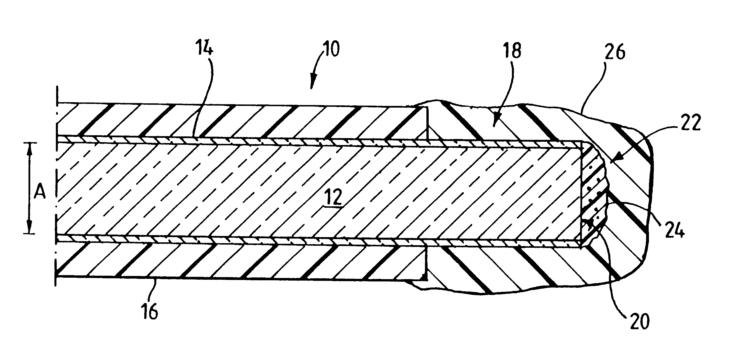
It has been found that the pattern of distribution of the fluorophor in a sensor embodying the invention is particularly effective in transmitting a high proportion of the light generated by the fluorophor back along the fibre for detection.
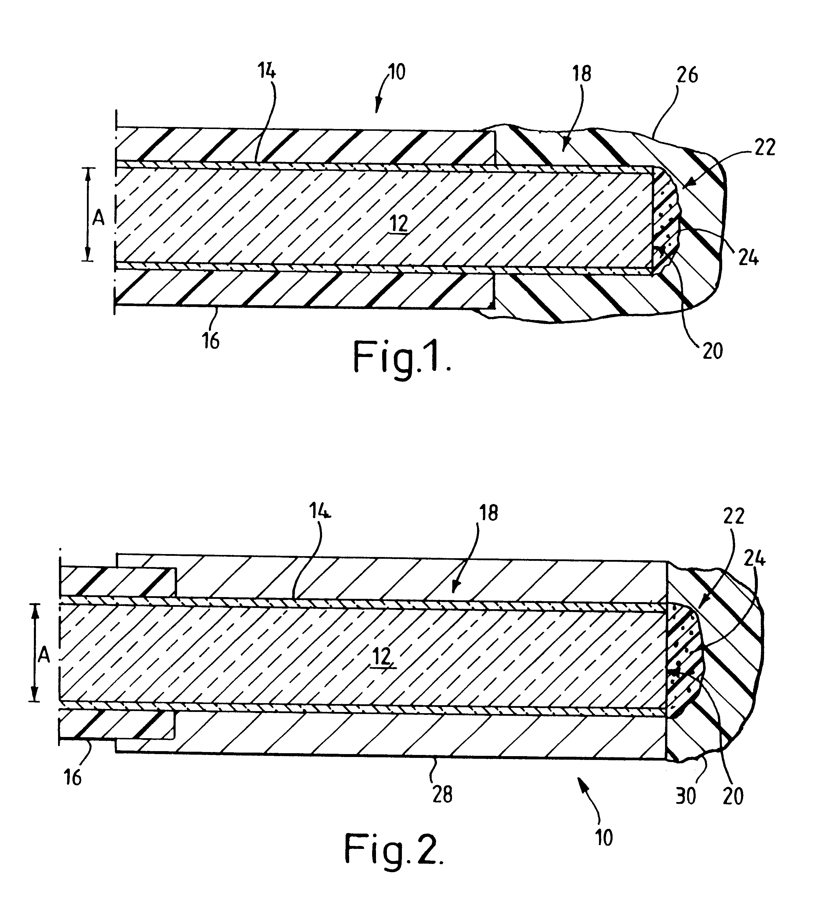
Alternatively, the method may include insertion of the said end portion through a hollow member, such that its end face, on which the liquid polymer is applied, projects from the hollow member, and subsequent to curing of the polymer layer, a protective coating is applied to cover an end face of the tubular member and the polymer body. The hollow member may be a hollow needle made, for example, from steel or a ceramic material. The arrangement described in this paragraph has the advantage of having high mechanical durability.
In most practical embodiments, the light source is operated repeatedly, the analysing means being operable to calculate an average value of a plurality of calculated concentration values. This arrangement ensures that random variations in any one measurement do not substantially affect the accuracy of the system.
This system is particularly useful in systems of the above defined aspects of the invention, but can also find application in other systems in which high-speed analysis of exponentially varying signals is needed. Its particular advantage is that the mathematically difficult task of performing the integration is carried out in high-speed, low-cost dedicated hardware. The computing means can therefore be of relatively low performance, since it need perform only a few mathematically simple operations.
The integrating circuits can conveniently be implemented as operational amplifier integrators.

Problems solved by technology

However, the apparatus does have a major disadvantage.
While laser sources are readily available, they are relatively costly, such that they represent a significant portion of the total cost of a sensor.
The computing means can therefore be of relatively low performance, since it need perform only a few mathematically simple operations.

Method used


Image

  • Measuring the concentration of a substance
  • Measuring the concentration of a substance
  • Measuring the concentration of a substance

Examples


Embodiment Construction

With reference to FIGS. 1 and 2, there is shown two alternative sensor arrangements which embody, or form part of various aspects of the invention.

The sensor 10 comprises an optical fibre which is formed from a light transmitting core 12 surrounded by a cladding 14. A protective buffer layer 16 surrounds the cladding 14 to give the fibre mechanical strength and robustness.

The diameter of the fibre, shown at dimension A, is approximately 200 .mu.m. For this exemplary embodiment, the particular fibre chosen was a TECS (t.m.) optical fibre manufactured by 3M (t.m.).

The fibre has an end surface 20. An end portion of the fibre 18, extending from the end surface 20, is bared of the buffer layer 16. On the end surface 20, there is formed a body 22. The body comprises a quantity of moulded polymer formed as a curved projection from the end surface 20. Within the body 22, a multiplicity of particles 24 are dispersed.

Each of the particles 24 is formed from silica gel. The average diameter of ...


PUM

PropertyMeasurementUnit
diameteraaaaaaaaaa
diameteraaaaaaaaaa
diameteraaaaaaaaaa

Abstract

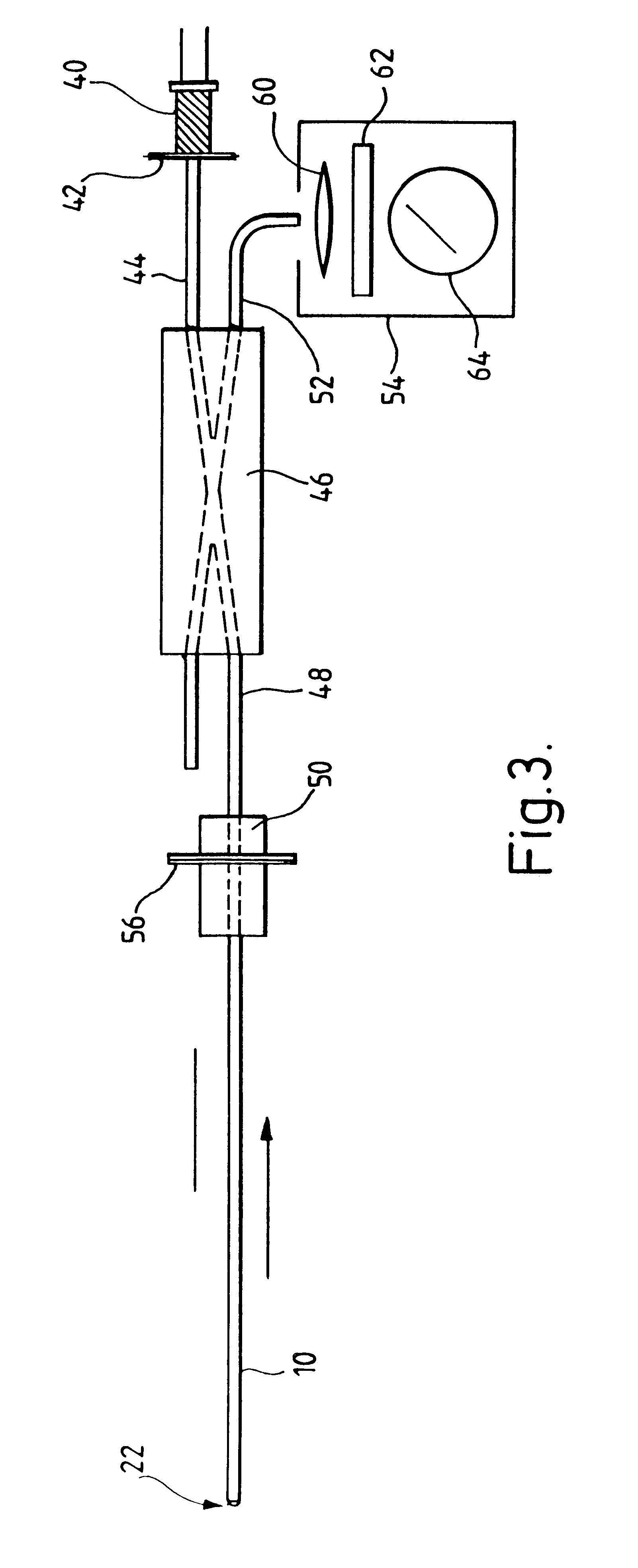
A system for measuring the concentration of an assay substance comprising a sensor having an optical fiber (10) on one end of which is coated a body (22). A fluorophor is dispersed within the body (22), the fluorescent activity of which is altered in relationship to the concentration of the assay substance. Light from a source such as an LED (40) is carried by the fiber (10) to the body (22). Light emitted by the fluorophor is carried to a detector unit (54) along the fiber (10). Concentration of the assay substance is determined by measurement of the characteristics of the growth in emitted light following activation of the LED (40).

Description

The present invention relates to an apparatus and a method for determining the concentration of a substance. In one particular application, the invention relates to apparatus and a method for determining the concentration of oxygen within living tissue cells.BACKGROUND TO THE INVENTIONFor clarity, the term "assay substance" will be used in this specification to refer to the particular substance that an apparatus or method according to the invention is intended to detect.It is well-known that a large number of fluorescent dyes measurably change their fluorescing characteristics in dependance upon the concentration of specific substances. For example, it is known that the fluorescence of the fluorophor tris(4,7-diphenyl-1,10-phenanthroline) ruthenium chloride is decreased in an inverse relationship to concentration of oxygen. It is recognised that both the intensity and the duration of light emitted by fluorescence of this substance are reduced in the presence of oxygen.This phenomeno...

Claims


Application Information

Patent Timeline
Patent Type & Authority Patents(United States)
IPC IPC(8): A61B5/00G01N21/77G01N21/64G01N21/78
CPCA61B5/1459A61B5/6848G01N21/6428G01N21/7703G01N21/6408G01N2021/772
Inventor VOJNOVIC, BORIVOJYOUNG, WILLIAM K.WARDMAN, PETER
Owner CANCER RES TECH LTD
Learn More