Method, system and apparatus for transmitting, receiving, and reproducing a digital broadcast signal

system technology, applied in the field of method, system and apparatus for transmitting, receiving, and reproducing a digital broadcast signal, can solve the problems of unrealistic for a user of the mobile unit to prepare such a signal, radio wave transmission path tends to suffer from radio wave cut, broadcast program suffers from reproduction interruption

Inactive Publication Date: 2003-03-18
FUJITSU LTD
View PDF8 Cites 144 Cited by
  • Summary
  • Abstract
  • Description
  • Claims
  • Application Information

AI Technical Summary

Problems solved by technology

Therefore, it was unrealistic for a user of the mobile unit to prepare such. an antenna to receive the satellite broadcasting.
Therefore, if these moving bodies pass an area near a building, a tree, a bridge, a tunnel or the like, the radio wave transmission path tends to suffer from radio wave cut due to an obstacle.
Further, if the receiver is utilized in a stationary fashion, the radio wave transmitted from the broadcasting station also will suffer from radio wave cut due to a moving obstacle, with the result that the broadcast program will suffer from reproduction interruption.
Therefore, the receiving side of the broadcast system cannot be provided with a satisfactory broadcasting service due to the disturbance in picture reproduction or audio reproduction.
Conversely, if sound reproduction is interrupted on the receiving apparatus, uncomfortable feeling of a listener cannot be relieved effectively with a relatively easy effort even if a countermeasure such as muting or the like is taken.
Particularly when an audio broadcasting is provided for mobile users and a driver of a vehicle is paying his/her attention to the reproduced sound intensively, the uncomfortable feeling due to the sound

Method used


Image

  • Method, system and apparatus for transmitting, receiving, and reproducing a digital broadcast signal
  • Method, system and apparatus for transmitting, receiving, and reproducing a digital broadcast signal
  • Method, system and apparatus for transmitting, receiving, and reproducing a digital broadcast signal

Examples


Embodiment Construction

.

Embodiments of the present invention will hereinafter be described with reference to the attached drawings.

(A) Description of the Embodiments of the Present Invention

FIG. 4 is a diagram showing an arrangement of a system including an S-band mobile digital broadcasting satellite to which the present invention is applied. The satellite broadcasting system shown in FIG. 4 is a system in which multimedia digital information such as music having a quality emulating that of a music reproduced from a compact disk, image data, text data or the like can be broadcast so as to be received all over Japan in a multi-channel fashion, and the broadcast data can be received by a vehicle or a portable terminal having no parabolic antenna. That is, a broadcast program is transmitted from a parabolic antenna 50b installed in a broadcast station 50a to a broadcasting satellite (or communication satellite) 51 by using a Ku-band (14 to 18 GHz band) (up-link). When the broadcast radio wave is transmitted...


PUM


Abstract

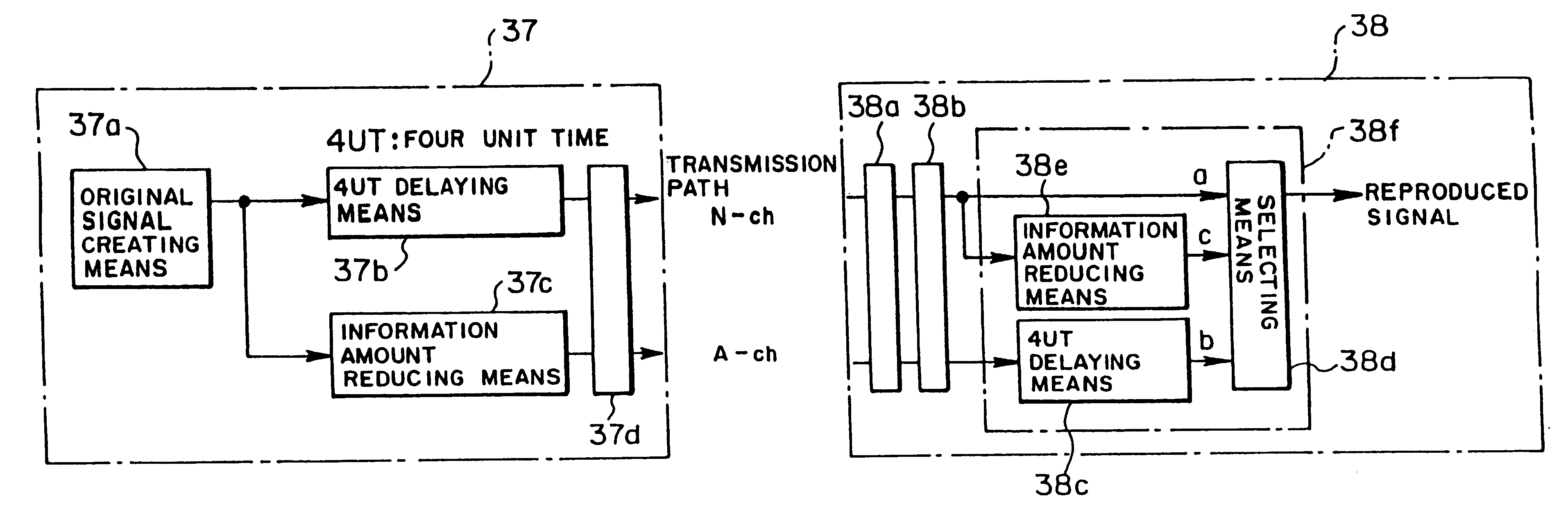
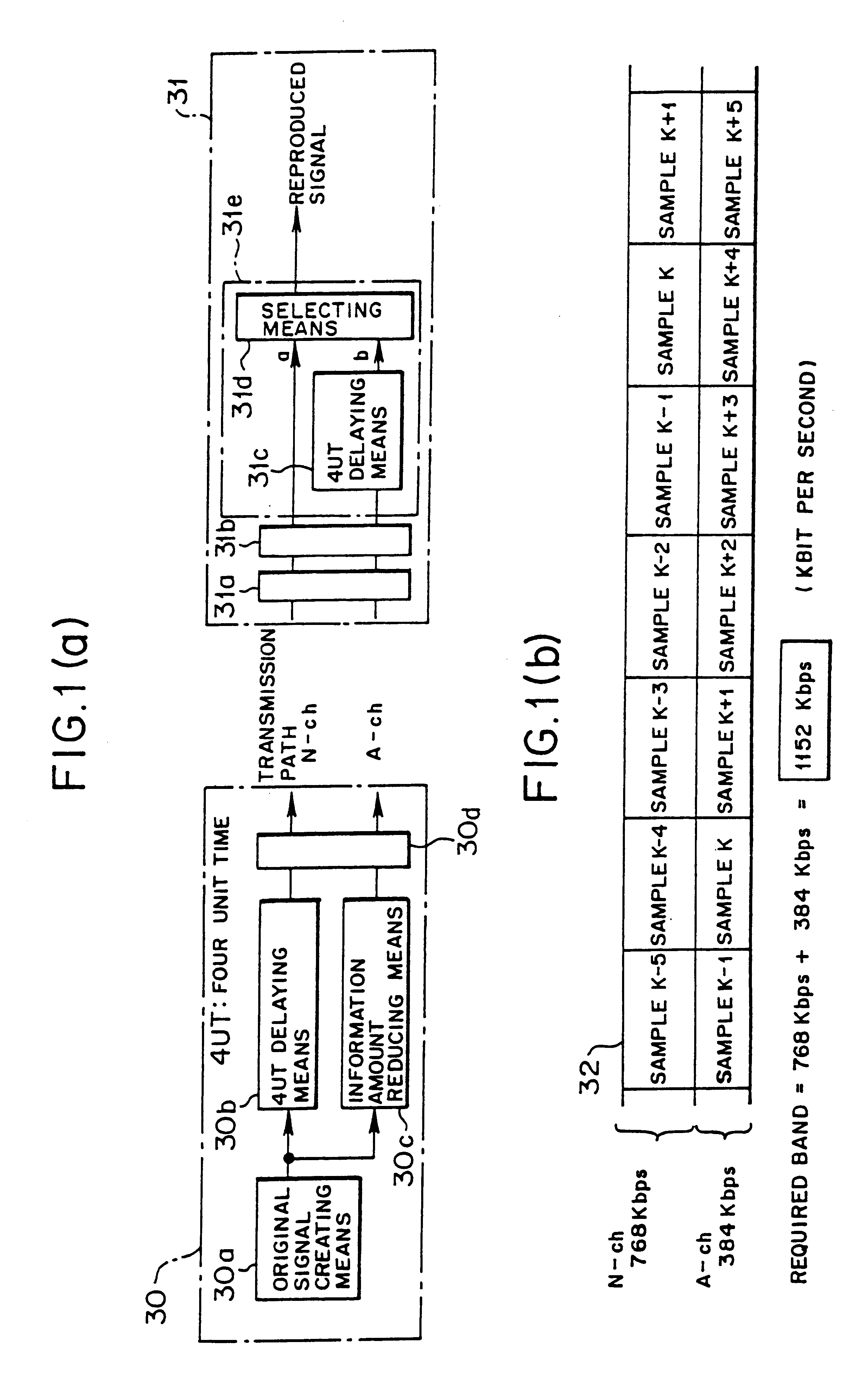
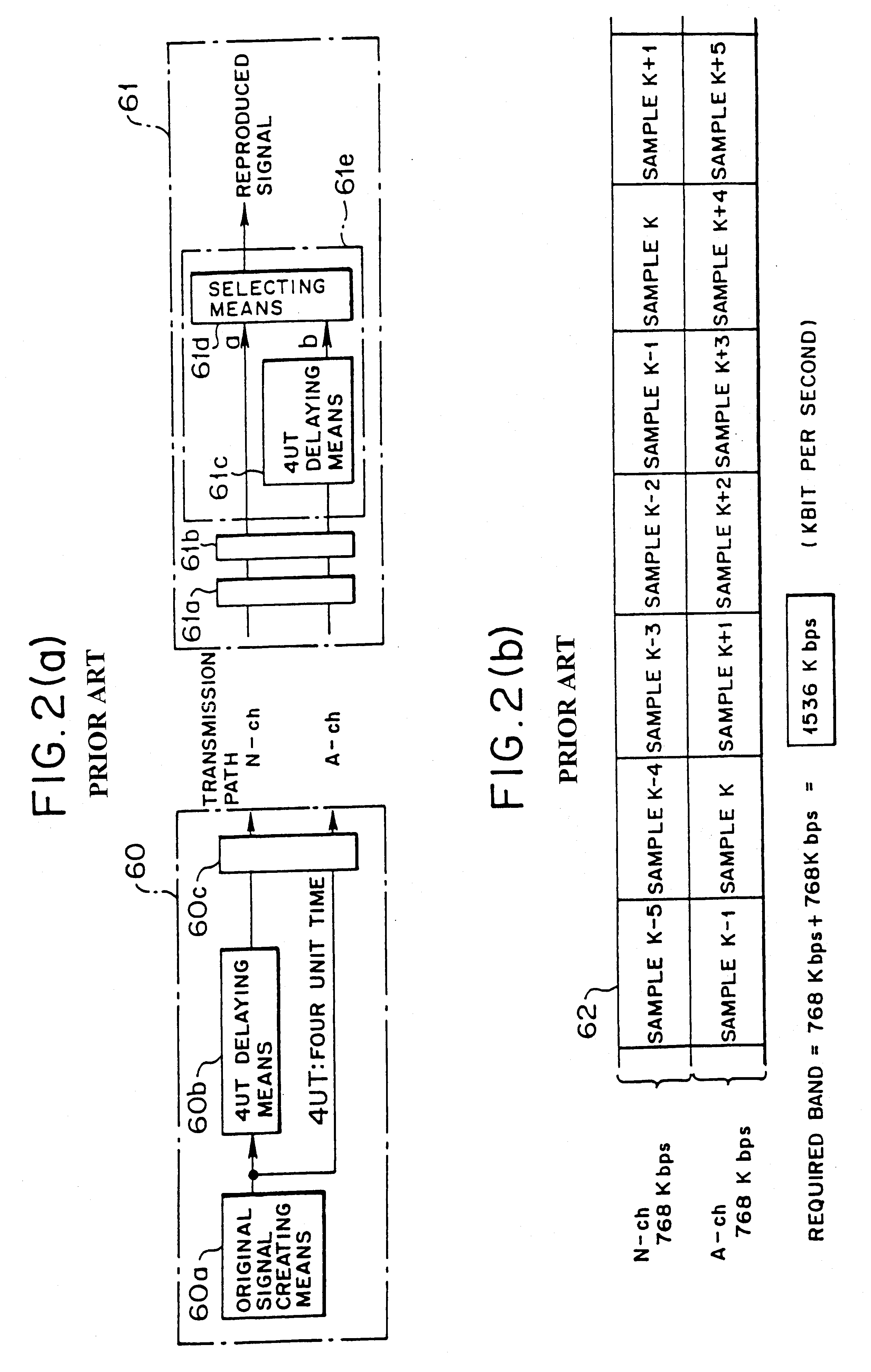
The present system comprises a transmitting apparatus for digital broadcast which includes an original signal generating section, delaying section, information amount reducing section, and transmitting section. A receiving and reproducing apparatus for digital broadcast includes a signal reception front stage unit for receiving a high quality signal and a low quality signal, mode determining section and reproducing section composed of a delaying section and selecting section for selectively reproducing the high quality signal and the low quality signal. By employing time diversity, the transmitting apparatus sends the low quality signal having a smaller bandwidth and the high quality signal so that the low quality signal has a preceding time lag relative to the high quality signal, and the receiving apparatus reproduces broadcasting programs. Utilizing the frequency band for broadcast effectively, many broadcasting programs can be increased, and the investment for providing a gap filler can be minimized.

Description

(1) Field of the InventionThe present invention relates to a method and system for transmitting a signal and receiving and reproducing the signal in a digital broadcasting situation, and a transmitting apparatus and a receiving and reproducing apparatus used in a digital broadcasting situation, suitable for a system for receiving digital satellite broadcasting by a receiver carried in a mobile unit.(2) Description of Related ArtRecently, in parallel with putting digital satellite broadcasting into practice, there have been developed and proposed various image data compression system, audio data compression system and the like. Also, there are discussed systems of various manner for receiving digital satellite broadcasting by a receiver carried in a mobile unit.When a satellite broadcasting is to be received, in general, it is necessary to prepare a parabolic antenna for receiving the radio wave of which frequency is allocated by the authority. Therefore, it was unrealistic for a use...

Claims


Application Information

Patent Timeline
IPC IPC(8): H04N7/58H04N7/26H04N7/52H04N7/64H04B1/74H04H20/00H04H20/16H04H20/28H04H20/74H04H60/12H04J3/00H04L1/02H04L1/08H04L1/22H04N7/08H04N7/081H04N7/173H04N19/00H04N19/102H04N19/12H04N19/126H04N19/166H04N19/196H04N19/423H04N19/59H04N19/65H04N19/80H04N19/85H04N19/89
CPCH04H20/16H04H20/28H04H20/74H04H60/12H04L1/04H04L1/08H04N19/89H04N21/2365H04N21/41407H04N21/4347H04N21/44209H04N19/30H04N21/23439
Inventor MATSUSHIMA, KAZUHISAYOKOYAMA, HIDEAKIOKUBO, HIROSHIKATOH, TADAYOSHISAITO, TAKASHI
Owner FUJITSU LTD
Why Eureka
Try Eureka