Method of grinding an axially asymmetric aspherical mirror

a technology of axial asymmetry and aspherical mirror, which is applied in the direction of optical surface grinding machines, manufacturing tools, abrasive surface conditioning devices, etc., can solve the problems of limiting the practical application of axially asymmetric aspherical mirror, large processing amount, and poor accuracy of processed surface with respect to reference surfaces

Inactive Publication Date: 2003-03-25
RIKEN +1
View PDF11 Cites 105 Cited by
  • Summary
  • Abstract
  • Description
  • Claims
  • Application Information

AI Technical Summary

Benefits of technology

By using a laser-type shape measuring device, the shape of the circular arc surface of the grindstone and the processed surface of the workpiece can be measured on the machine with a high accuracy from a location some distance away from the machine. On the other hand by using the contact-type shape measuring device, on-machine measurements can be made reliably even under adverse conditions.

Problems solved by technology

However, the conventional means of producing such an ultra-precision mirror surface require a very long time (for instance, several months or more), consequently, this restricts the practical application of axially asymmetric aspherical mirrors, and this is a practical problem.
However, the polishing allowance normally required is about 10 times the surface roughness before processing, so, in practice, a depth of 10.about.20 .mu.m must be removed by polishing, that is, the processing amount is very large.
When an amount of 10.about.20 .mu.m is removed by polishing, the residual stress on the surface caused by lapping or grinding is removed, therefore the accuracy of the processed surface with respect to a reference surface becomes worse, and this is another problem.
Still another problem is that while repeating these operations, the reference surface of an optical element is often changed.
A curved surface with a large radius of curvature is processed on the surface of a rectangular block of raw material (quartz etc.) Therefore if a processing tool, for instance, a pole-nose grindstone is used that rotates around an axis normal to the surface of the raw material (upper surface in FIG. 2C), the processing efficiency at the center of the lower surface is low resulting in an inferior surface roughness.
Conversely, if a processing tool, for instance, a cylindrical grindstone is used which rotates about an axis parallel to the surface of the raw material (upper surface in FIG. 2C), the axis of rotation must be long to avoid interference with the raw material, and the accuracy of the process is poor due to the effect of shaft deformation.

Method used


Image

  • Method of grinding an axially asymmetric aspherical mirror
  • Method of grinding an axially asymmetric aspherical mirror
  • Method of grinding an axially asymmetric aspherical mirror

Examples


Embodiment Construction

Preferred embodiments of the present invention are described referring to the drawings. In each drawing, common portions are identified with the same reference numbers, and duplicate descriptions are omitted.

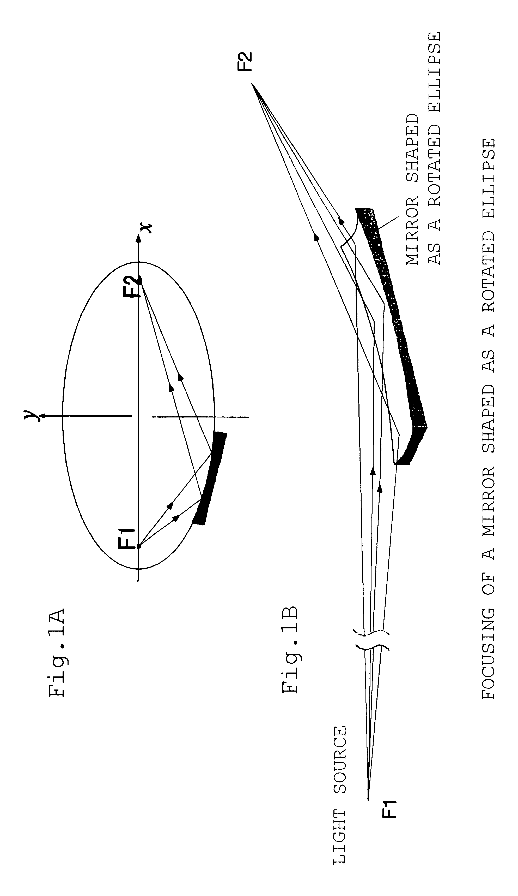
FIG. 3 is a flow chart for processing an axially asymmetric aspherical mirror. As shown in FIG. 3, the raw material must be prepared, and grinding and polishing processes are required to produce the axially asymmetric aspherical mirror. Although the following embodiments are described using a mirror with a rotated elliptical surface as example of an axially asymmetric aspherical mirror, the present invention should not be limited only to this mirror, but the invention can also be applied to reflecting mirrors with axially asymmetric aspherical surfaces known in the prior art, including rotated parabolic surfaces and rotated hyperbolic surfaces.

Referring to FIG. 3, the raw material of an axially asymmetric aspherical mirror is prepared by selecting from the following materials--c...


PUM

PropertyMeasurementUnit
diameteraaaaaaaaaa
diameteraaaaaaaaaa
roughnessaaaaaaaaaa

Abstract

An electrolytic in-process dressing device 10 is provided with a disk-shaped metal-bonded grindstone 2 with a surface 2a with a circular arc shape with a radius R at its outer periphery and a numerical control device 16. The disk-shaped metal-bonded grindstone 2 rotates around an axis Y, and the grindstone is dressed electrolytically while the device 10 grinds the workpiece 1. The numerical control device 16 is provided with a rotary truing device 12 that rotates around the X axis that orthogonally crosses the axis of rotation Y and trues the circular arc surface 2a, a shape measuring device 14 for measuring the shape of the circular arc surface of the grindstone and the shape of the processed surface of workpiece 1 on the machine, and controls the grindstone numerically in the three directions along the axes X, Y and Z. The numerical control device 16 moves the grindstone in three axial directions and repeats the operations of truing, grinding and measurements on-line. Thus, an axially asymmetrical aspheric mirror with a highly accurate shape and extremely low surface roughness, that can precisely reflect or converge light can be manufactured within a short time with a high accuracy.

Description

1. Technical Field of the InventionThe present invention relates to a method of grinding an axially asymmetric aspherical mirror.2. Prior ArtA reflecting mirror with an axially asymmetric aspherical surface such as an elliptical surface, parabolic surface or hyperbolic surface (called an axially asymmetric aspherical mirror) is used as an optical element that reflects, focuses or disperses X-rays, laser light, visible light, etc. For instance the mirror with a surface formed by rotating an ellipse shown in FIG. 1A has two focal points F1, F2, and has the intrinsic characteristic that light passing from one focal point F1 is reflected by the elliptical surface of the mirror and travels to the other focal point F2. This elliptical surface mirror also has the characteristic that the mirror converges the light from the focal point F1 into the focal point F2 with high precision. More precisely, as shown in FIG. 1B, a light source with a diameter of 1 mm, for example, located at the focal...

Claims


Application Information

Patent Timeline
Patent Type & Authority Patents(United States)
IPC IPC(8): B24B13/00B24B53/00B24B53/06B24B13/06B24B53/08B24B49/04B24B49/02B24B49/12B23H5/00B24B11/00B24B49/18
CPCB24B13/06B24B53/08B24B53/001B24B49/04B24B11/00
Inventor OHMORI, HITOSHIYAMAGATA, YUTAKAMORIYASU, SEIMORITA, SHINYAKADA, KATSUHIKOKIRA, HIDETAKASASAI, HIROYUKIKAWATA, MASARU
Owner RIKEN
Why Eureka
Try Eureka