
Method of screen printing stencil production

a stencil and screen printing technology, applied in the direction of printing process, duplicating/marking method, decorative arts, etc., can solve the problems of time-consuming and laborious screen production, black parts of the positive not allowing light, and normal lighting cannot be used throughout the screen production process in any method

Inactive Publication Date: 2003-04-01
AUTOTYPE INT
View PDF24 Cites 55 Cited by
  • Summary
  • Abstract
  • Description
  • Claims
  • Application Information

AI Technical Summary

Benefits of technology

This method reduces production time and labor, eliminates the need for actinic lighting, and allows for normal lighting use, resulting in a more efficient and cost-effective stencil production process.

Problems solved by technology

The black portions of the positive do not allow light to penetrate to the emulsion which remains soft in those areas.
One problem generally associated with all the prior art methods is that many steps are necessary to produce the screen, thus making screen production time-consuming and labour-intensive.
Another problem is that normal lighting cannot be used throughout the screen production process in any of the methods except hand cutting.
This usually incurs a penalty of initial cost, space utilisation and ongoing maintenance costs.
Both the above methods require the use of very specialised equipment (because of the need to handle large complete screens) which incurs a certain cost as well as imposing restrictions arising from the limitations of the equipment, in particular in terms of the size of screen and its resolution.

Method used


Image

  • Method of screen printing stencil production
  • Method of screen printing stencil production
  • Method of screen printing stencil production

Examples


example 1

Polyethylene terephthalate film base of 75 .mu.m thickness was coated with a layer of the following dispersion at a thickness of 0.5 to 1 .mu.m using 0.010 in Meyer bar, in order to provide a release layer:

The coated film base was then coated on the release layer side with the following first coating composition to a thickness of 8 .mu.m using a 0.050 in Meyer bar:

The first coating composition was dried using a warm fan operating at 40.degree. C. to give a first coating layer on the polyethylene terephthalate film base. The following second coating composition was then coated onto the first coating layer to a thickness of 5 .mu.m using a 0.020 in Meyer bar:

The coated composition was dried using a warm air fan operating a 40.degree. C. to give a receptor element having a two-layer stencil forming coating. The following imaging composition was prepared and introduced to an ink-jet printer cartridge suitable for use in a Hewlett Packard 550 ink-jet printer.

The cartridge was fitted to t...

example 2

Example 1 was repeated exactly except that the following imaging composition was prepared and used:

The final screen was again robust with no reticulation and was found capable of printing more than 500 copies on paper using a commercial screen-printing ink.

example 3

Example 1 was repeated exactly except that the following single coating composition was used instead of the first and second coating compositions of example 1.

This composition was coated on the sub-layer of example 1 at a coating thickness of 11 .mu.m using a 0.065 in Meyer bar. The final screen was robust with no reticulation and was found capable of printing more than 500 copies on paper using a commercial screen-printing ink.


PUM

PropertyMeasurementUnit
wt. %aaaaaaaaaa
thicknessaaaaaaaaaa
thicknessaaaaaaaaaa

Abstract

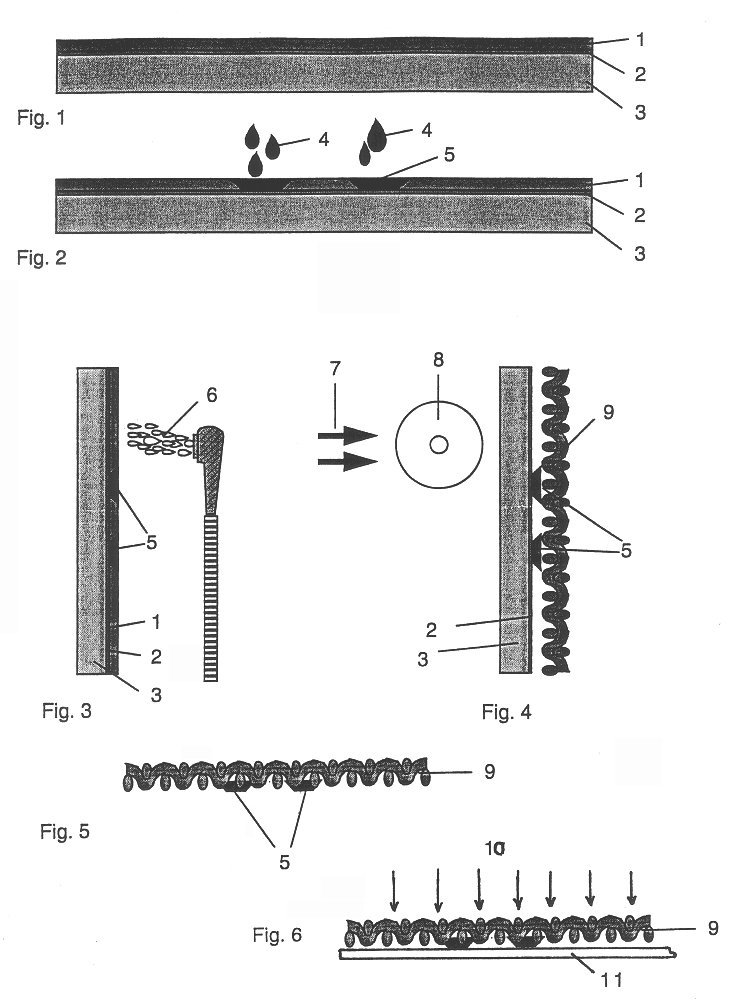
A coated film product comprises a support base, a stencil-forming layer and an intermediate release layer. The stencil-forming layer is a blend of two grades of polyvinyl alcohol having different degrees of hydrolysis. The stencil-forming layer is imaged by dropwise application (for example using an ink-jet printer or plotter) of a cross-linking agent which hardens the stencil-forming layer to resist washing out with water. The hardened areas remaining after washing out are however sufficiently tacky for the washed-out film to adhere to the screen mesh by application of pressure and, after removal of the support base, form the stencil layer of a screen-printing screen.

Description

BACKGROUND TO THE INVENTION1. Field of the InventionThe present invention relates to the production of stencils for screen printing.2. Related Background ArtThe production of screen printing stencils is generally well known to those skilled in the art.One method, referred to as the "direct method" of producing screen printing stencils involves the coating of a liquid light-sensitive emulsion directly onto a screen mesh. After drying, the entire screen is exposed to actinic light through a film positive held in contact with the coated mesh in a vacuum frame. The black portions of the positive do not allow light to penetrate to the emulsion which remains soft in those areas. In the areas which are exposed to light, the emulsion hardens and becomes insoluble, so that, after washing out with a suitable solvent, the unexposed areas allow ink to pass through onto a substrate surface during a subsequent printing process.Another method, referred to as the "direct / indirect method" involves c...

Claims


Application Information

Patent Timeline
Patent Type & Authority Patents(United States)
IPC IPC(8): B41C1/14B41C1/00B41C1/10B41N1/24G03F7/12
CPCB41C1/003B41C1/1066B41C1/147Y10T428/24802Y10T428/263Y10T428/31725
Inventor JONES, JOHN W.FOSTER, DAVID JOSEPH
Owner AUTOTYPE INT
Learn More