
Vented aspirator and method

a technology of aspirator and tube, which is applied in the field of surgical instruments, can solve the problems of fragments and fluids moving not at all or very slowly through the cannula and suction tube, clogging the tubing, and affecting the quality of the suction tube, so as to prevent clogging, eliminate clogging problems, and facilitate aspiration.

Inactive Publication Date: 2003-04-01
SOUND SURGICAL TECH
View PDF16 Cites 24 Cited by
  • Summary
  • Abstract
  • Description
  • Claims
  • Application Information

AI Technical Summary

Benefits of technology

It is a further object of the present invention to provide a surgical instrument for the above-mentioned purpose that causes minimal trauma to all contacted tissues and thus provides decreased healing time, decreased patient pain, and reduced swelling, bleeding, and bruising.
The aforementioned objects of the present invention are accomplished by separating the tissue fragmentation aspect of the liposuction procedure from the aspiration aspect of the procedure and by providing a pressure vent capability using a multi-lumen cannula that prevents clogging.
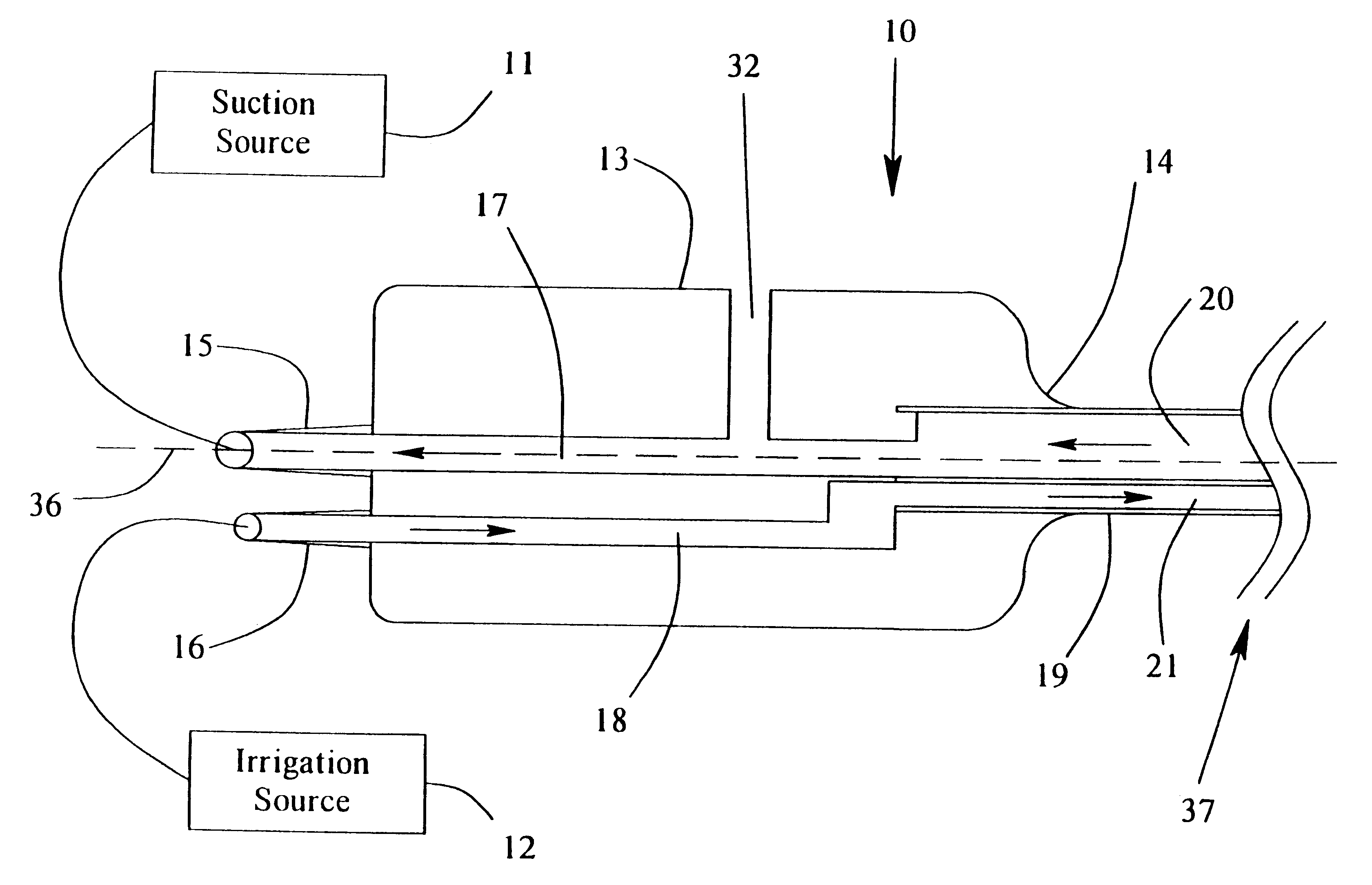
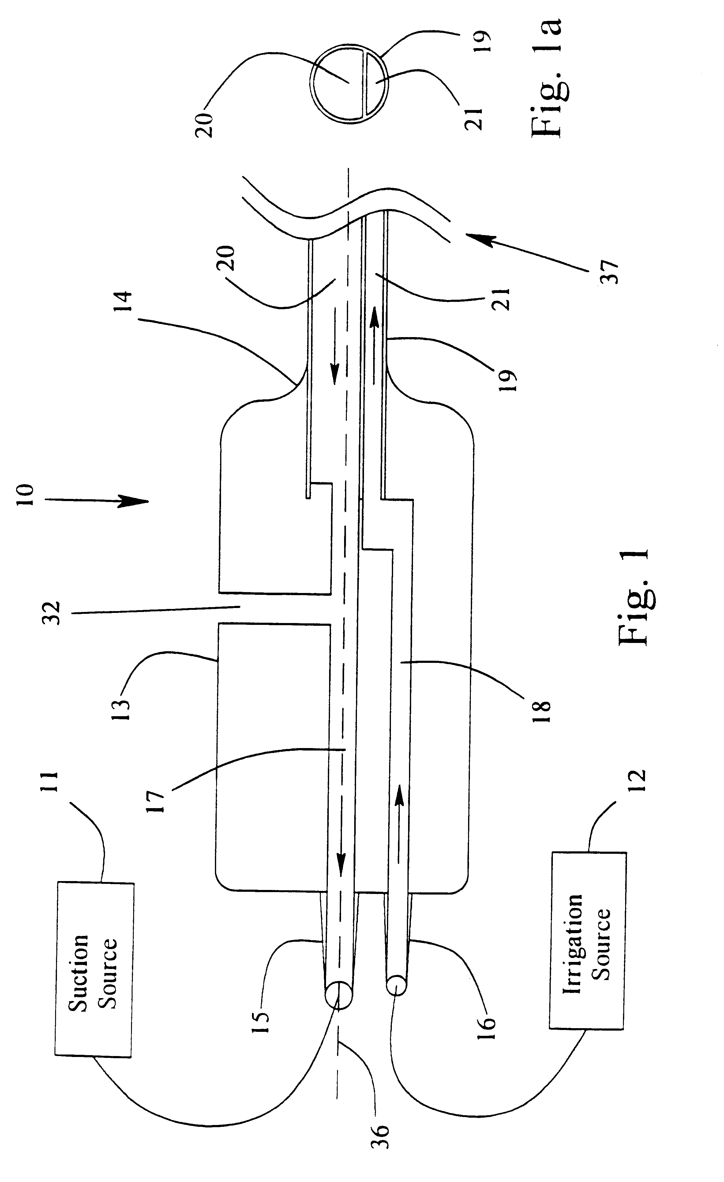
The multi-lumen cannula may include a patient tip disposed away from the distal end of the handle with a blunt or bullet-nosed shape. The blunt or bullet-nosed shape of the tip is to smooth passage of the multi-lumen cannula through the tissues, thereby reducing trauma to the tissues and reducing the force required by the surgeon to push the multi-lumen cannula through the tissues. The preferred material for the patient tip is stainless steel. Polymers such as polycarbonate, polyurethane, or polyethylene may also be used. There may be one or more ports in or near the patient tip for providing fluid communication between the tissue and the first passage of the multi-lumen cannula. The one or more ports may be part of the patient tip or they may be part of the multi-lumen cannula near the patient tip. There may be one or more holes in or near the patient tip for providing fluid communication between the second passage of the multi-lumen cannula and the tissue. The one or more holes may be part of the patient tip or they may be part of the multi-lumen cannula near the patient tip.

Problems solved by technology

First, they crush, tear, or avulse the fatty tissues such that the tissue fragments and fluids can pass through the openings in the sides of the cannula.
Thus, fragments and fluids move not at all or very slowly through the cannula and suction tubing, or clog the tubing.
The liposuction procedure can be traumatic to the patient.
The mechanical disruption of the tissues may result in, among other things, bleeding, bruising, temporary numbness, or swelling.
The procedure can also be physically demanding on the surgeon because of the forces required to repeatedly push the cannula through the tissue.
This patent includes a means to vent the tubing set from the handpiece back to the suction source, but does nothing to solve the same problem for the cannula.
Consequently, the seal and clog problems persist.
While some of the patented devices have claimed improvements and solutions to liposuction cannulae for the problems of tissue trauma, surgeon fatigue, and cosmetic results, none address or appreciate the above-mentioned seal and clog problems and all of the prior devices incorporate tissue fragmentation and tissue aspiration capability in but one cannula.
All of these devices are subject to clogging.

Method used


Image

  • Vented aspirator and method
  • Vented aspirator and method
  • Vented aspirator and method

Examples


Embodiment Construction

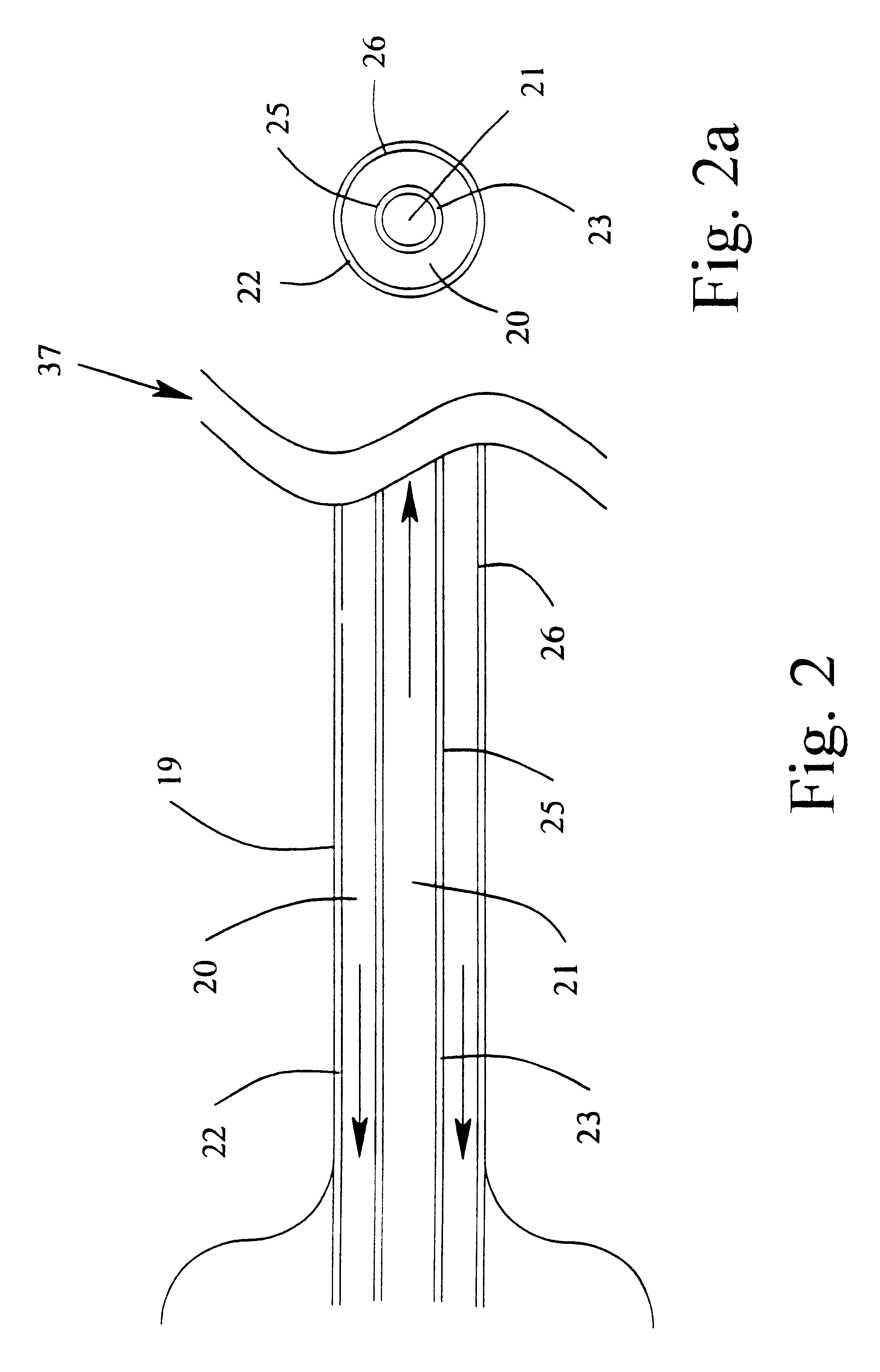
Referring to the drawings, FIG. 1 is a partial schematic representation of the apparatus embodying this invention. In general the surgical aspirator and irrigator system 10 is comprised of a source of suction 11, a source of irrigation fluid 12, and a handle 13 to be held and manipulated by the surgeon. The source of suction may be the wall suction present in the operating room or it may be from a separate suction pump specifically designed for the lipoplasty procedure. The preferred method to deliver the irrigation fluid is to use a peristaltic pump and tubing set. The handle 13 has a suction connector 15 for fluid communication with the source of suction 11 and an irrigation connector 16 for fluid communication with the source of irrigation fluid 12. The preferred connector for both suction and irrigation is a tubing barb threaded into the handle 13. The handle 13 has a suction channel 17 in fluid communication with the suction connector 15, an irrigation channel 18 in fluid commu...


PUM


Abstract

An improved surgical instrument for the removal of previously fragmented tissues and fluids from a patient through a small incision including a multi-lumen cannula, one lumen of which is used to supply an irrigating fluid to suspend and dilute the fragmented tissue and the other lumen for the application of suction to remove the tissue and fluids. The second lumen has a resistive ratio that is between 0.5 and 1.5 times the resistive ratio of the first lumen.

Description

I. BACKGROUNDThis invention relates generally to surgical instruments, and, more particularly, to a surgical device for use in aspirating fragmented tissue and fluids from a patient.Liposuction is a surgical procedure for altering the human form, specifically by removal of localized deposits of fat tissues that are unresponsive to diet or exercise. The procedure is also known as suction lipectomy, lipolysis, and more recently as body contour surgery or body sculpting surgery. It is most often performed by plastic surgeons, although dermatologists, gynecologists, and other surgical specialties also perform the procedure.The procedure is typically accomplished by inserting a small cannula through an incision in the skin, applying a suction source to the end of the cannula that remains outside of the body, and forcing the working end of the cannula forward and backward in the layer of fatty tissue. The fatty tissue is torn, crushed, or avulsed, and is then aspirated through small openi...

Claims


Application Information

Patent Timeline
IPC IPC(8): A61M1/00
CPCA61M1/0047A61M1/0084A61M1/0064A61M1/7411A61M1/774A61M1/85
Inventor CIMINO, WILLIAM W.
Owner SOUND SURGICAL TECH
Learn More