Ultrasonic probe

a technology of ultrasonic probes and probes, applied in the field of ultrasonic probes, can solve the problems of reducing the efficiency of transmitting and receiving ultrasonic waves, and affecting the damping effect of backing materials

Inactive Publication Date: 2003-04-22
KONICA MINOLTA INC
View PDF15 Cites 34 Cited by
  • Summary
  • Abstract
  • Description
  • Claims
  • Application Information

AI Technical Summary

Problems solved by technology

Accordingly, there occurs a problem in that the efficiency in transmitting and receiving the ultrasonic wave is reduced, and further the frequency characteristic is degraded.
Further, there is another problem in that an insulator of a signal electrical terminal disposed between the piezoelectric element and the backing material is generally thick, which has a negative effect on the damping of the backing material and degrades the acoustic characteristic of the ultrasonic probe, especially the frequency characteristic thereof.
However, the acoustic matching is impaired and the pulse length and the propagation efficiency are degraded due to an existence of the ground electrode side conductive layer 40 made of metallic material between the acoustic matching layer 37 and the acoustic lens 38.
This problem is also seen at the positive electrode side conductive layer.
The conductive layer has a greater adverse effect as the frequency of the ultrasonic wave increases.
On the other hand, however, the thinner conductive layer makes the electrical resistance (electrical impedance) larger, and thereby a driving electrical signal on an electrical conductive path is lowered to reduce the electrical signal applied to the piezoelectric element 1, and as a result, the electro-mechanical conversion efficiency from a viewpoint of the diagnostic apparatus is decreased.
Further, when the electrical impedance on the electrical conductive path is increased, the capability of removing external electrical noise is deteriorated, and accordingly, external electromagnetic noise causes the diagnosis image to be deteriorated, which makes the simultaneous optimization of an acoustic matching condition and an electrical conductive path more difficult, and also prevents an accurate diagnosis based on the ultrasonic image, which eventually might result in a serious problem of inducing a wrong diagnosis.
Further, in the conventional system, since the electrodes are disposed on respective end faces of the piezoelectric element with respect to the short axis direction thereof, and are extended out therefrom, if the piezoelectric element is subjected to, for example, an external mechanical impact by a post-processing operation or the like, and thereby the first electrode fails to keep an electrical connection due to breakage thereof, the ability of transmitting and receiving the ultrasonic wave by the piezoelectric element is limited to only a portion of the electrode electrically connected to the copper foil or the FPC, and this sometimes causes to lower the performance of the piezoelectric element.
Further, since the copper foil and the FPC are electrically connected by a conductive adhesive or the like at end faces of the piezoelectric element with respect to the short axis thereof, sometimes another problem results in that, when a conductive adhesive of high curing temperature is employed, an electrode is deteriorated by heat and thereby the performance of the piezoelectric element is lowered.
Further, in the conventional ultrasonic probe described above, there is another problem that an insulator of the signal electrical terminal disposed between the piezoelectric element and the backing material is generally thick, which has a negative effect on the damping performance of the backing material, and degrades the acoustic characteristic of the ultrasonic probe, especially the frequency characteristic thereof.

Method used


Image

  • Ultrasonic probe
  • Ultrasonic probe
  • Ultrasonic probe

Examples


first embodiment

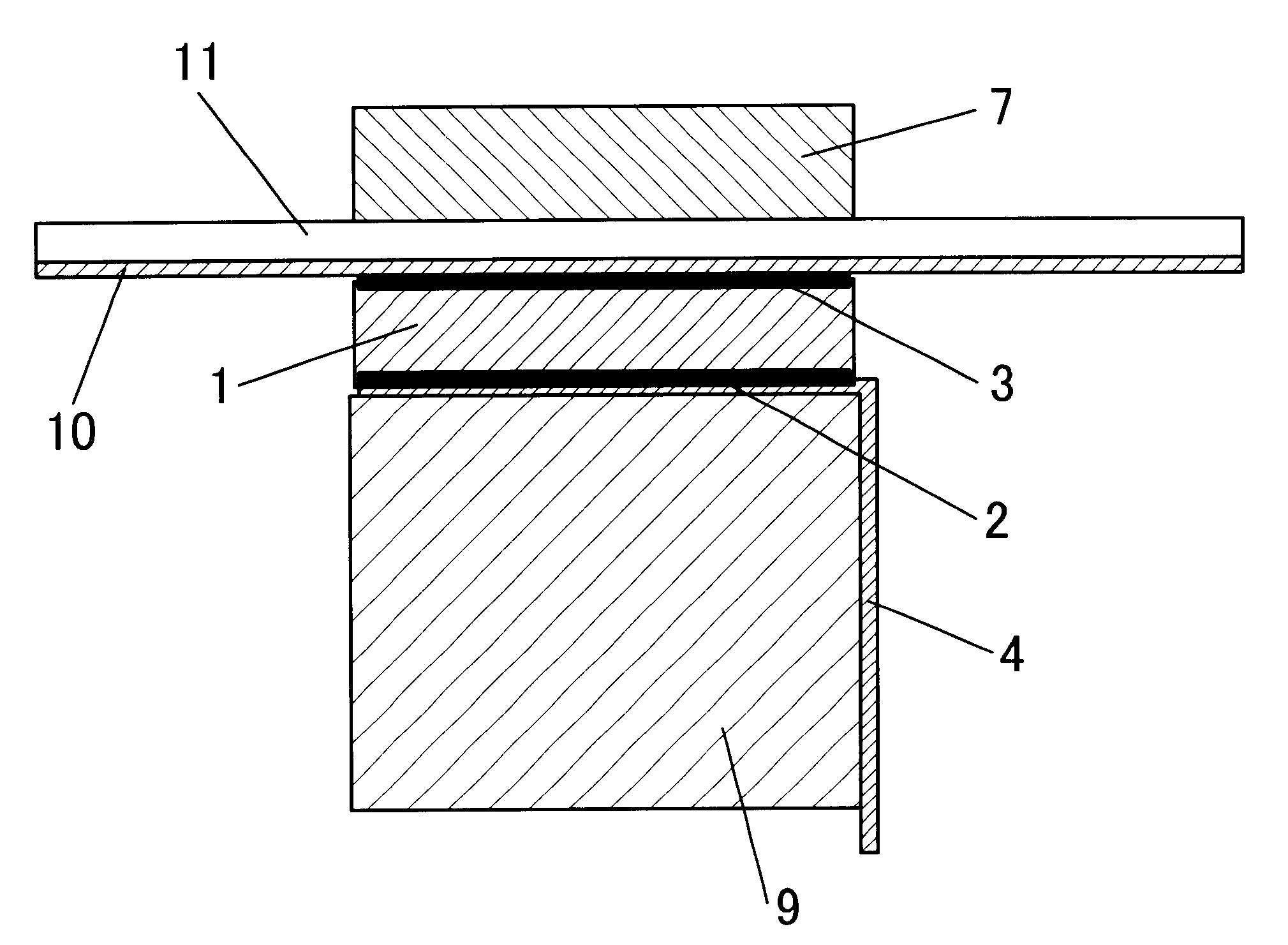
FIG. 1 is a schematic cross sectional view of an ultrasonic probe of a first embodiment according to the present invention.

Referring to FIG. 1, the piezoelectric probe of the present invention comprises: a piezoelectric element 1 for transmitting and receiving a ultrasonic wave, which is made of a piezoelectric ceramic including PZT-based material, single crystal or high molecular material such as PVDF (poly-vinylidene fluoride); a ground electrode 3 formed on one surface of the piezoelectric element by depositing or sputtering gold or silver thereon, or by baking silver thereon; a positive electrode 2 formed on the other surface of the piezoelectric element by depositing or sputtering gold or silver thereon, or by baking silver thereon, same as with the ground electrode 3; a signal electrical terminal 4 extended from the positive electrode 2; a backing material 9 for mechanically holding the piezoelectric element 1 and for functioning to dampen undesired ultrasonic signals; a high ...

second embodiment

the present invention is an ultrasonic probe in which a high molecular material layer having a conductive layer formed thereon is a first acoustic matching layer provided on one electrode surface of a piezoelectric element, and a second acoustic matching layer for the conductive layer to be electrically connected to the first acoustic matching layer, wherein the acoustic impedance of the high molecular material layer is substantially equal to that of the second acoustic matching layer. The second embodiment provides a high quality ultrasonic probe which allows an electrical terminal to be easily extended from an electrode of the piezoelectric element, and also allows good sensitivity and frequency characteristics in transmitting and receiving an ultrasonic wave to be secured because the high molecular material also serves as a part of the acoustic matching layer. The second embodiment further prevents a possible fault caused by a breakage of wire even if the piezoelectric element is...

third embodiment

the present invention provides an ultrasonic probe which allows an electrical terminal to be easily extended from an electrode of the piezoelectric element, and also allows good sensitivity and frequency characteristics in transmitting and receiving the ultrasonic wave to be secured because the high molecular material also serves as a part of the acoustic matching layer. The third embodiment further makes it possible to reduce noise since a shield effect is enhanced by a conductive layer formed on a face of the high molecular material layer located on an acoustic matching layer side.

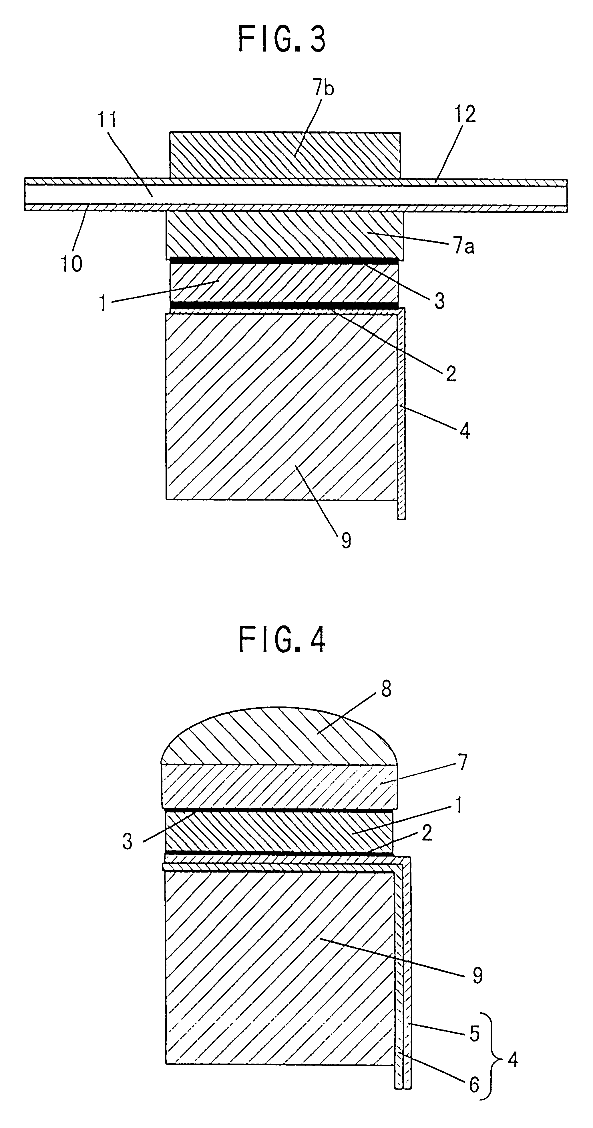
Referring to FIG. 3, reference numerals 1 to 11 are similar to those of the first and second embodiments shown in FIGS. 1 and 2. That is, the ultrasonic probe of the third embodiment of the present invention has a piezoelectric element 1, a ground electrode 3, a positive electrode 2, a signal electrical terminal 4, a backing material 9, a high molecular material layer 11, a conductive layer 10, a first a...


PUM


Abstract

Disclosed is an ultrasonic probe of high performance and high quality. The ultrasonic probe comprises a high molecular material having a conductive layer and is disposed between a piezoelectric element and an acoustic matching layer. The high molecular material has an acoustic impedance substantially equal to that of the acoustic matching layer. The ultrasonic probe thus configured can be formed into a slim shape which is easy to operate without degrading the performance thereof, such as sensitivity or frequency characteristics or the like. The ultrasonic probe is structured so as not to cause an electrical problem due to breakage of wire even if the piezoelectric element is cracked by a mechanical impact or the like, and thus a high quality ultrasonic probe can be provided, and noise can be reduced.

Description

The present invention relates to an ultrasonic probe to be used in an ultrasonic diagnostic apparatus or the like.DESCRIPTION OF THE PRIOR ARTAn ultrasonic probe is used, for example, in an ultrasonic diagnostic apparatus for a human body. One of the conventional ultrasonic probes is disclosed in Japanese Patent Laid-Open Publication No. Hei 8-122310. FIG. 17 shows a structure of this conventional ultrasonic probe. In FIG. 17, a piezoelectric element 31 is an element for transmitting and receiving an ultrasonic wave, and each face thereof is provided with an electrode. An acoustic matching layer 37 is made of conductive material and is provided on a face of one of the electrodes to efficiently transmit and receive an ultrasonic wave for a subject to be examined (human body). The ultrasonic probe further comprises a conductive layer 40 provided on a high molecular film 41 by deposition or other proper operations so as to be brought into contact with the acoustic matching layer 37. An...

Claims


Application Information

Patent Timeline
Patent Type & Authority Patents(United States)
IPC IPC(8): B06B1/06G10K11/02G10K11/00
CPCG10K11/02B06B1/067
Inventor SAITO, KOETSUKOISHIHARA, YASUSHITAKEDA, JUNICHIFUKASE, HIROKAZU
Owner KONICA MINOLTA INC
Why Eureka
Try Eureka