Method and device for controlling an internal combustion engine

a technology of internal combustion engine and control device, which is applied in the direction of electric control, control device, vehicle components, etc., can solve the problems of reducing the engine speed to idle speed, reducing the engine speed quickly, and particularly problematic changes to the lower gears, so as to avoid the speed decrease, reduce the cost, and simplify the structure

Inactive Publication Date: 2003-05-06
SCANIA CV AB
View PDF9 Cites 3 Cited by
  • Summary
  • Abstract
  • Description
  • Claims
  • Application Information

AI Technical Summary

Benefits of technology

Advanced control systems have recently been developed which adapt the engine speed to the input speed of a gearbox unit on the basis of a number of sensors situated at various points in the driveline, but these systems are applied in such a way that the clutch is not used in normal driving and the speed adjustment is designed to be so accurate that a gear changeover can be initiated directly without operating the clutch. Such sophisticated control systems are relatively expensive, however, since they require a more complex structure as regards both the components involved and the software programming of the control system. With the system according to the present invention, engine speed adjustment or maintenance is initiated by the driver operating an entirely manual or a servo-assisted clutch, but the clutch is otherwise used in a conventional manner. The advantage of the present invention is thus that it avoids the speed decrease which occurs with conventional systems, and hence also avoids the problems associated with the latter. The invention may thus be used at relatively low cost and in a simple manner without the control system becoming complex.

Problems solved by technology

When driving a heavy vehicle, such as a truck or a bus, provided with a mechanical gearbox and a mechanical clutch, e.g. of disc type, changing down to lower gears is particularly problematical.
Depressing the clutch pedal at the time of gear changing results in the engine speed decreasing quickly when the accelerator pedal is released, partly because of the internal friction in the engine.
A large number of successive gear changes further reduces the engine speed to idling speed.
A disadvantage of the state of the art is that the sometimes large speed differences and masses involved in such speed adjustment cause considerable clutch wear, even in normal gear changes during normal driving, owing to the aforesaid engine speed reduction when gear changing is initiated.
In addition, there is loading of all the other parts of the driveline and inducing of oscillations in the driveline.
These result in inferior comfort because of disturbing noise and physical vibration in the vehicle, which is particularly troublesome if the vehicle is a bus.

Method used


Image

  • Method and device for controlling an internal combustion engine
  • Method and device for controlling an internal combustion engine
  • Method and device for controlling an internal combustion engine

Examples


Embodiment Construction

This description exemplifies the use of the invention in a vehicle, such as a heavy-duty truck or a bus, in which a combustion engine is used as drive engine for the vehicle, and the vehicle's driveline incorporates a clutch between the engine and the gearbox. The engine may for example take the form of a diesel engine.

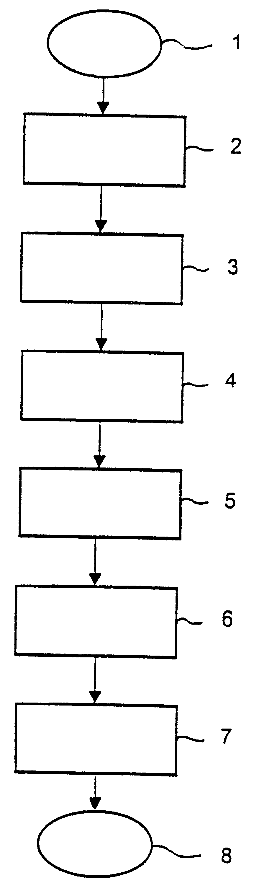
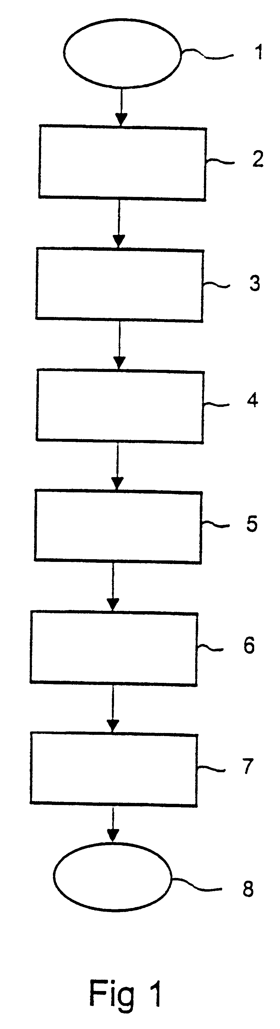
FIG. 1 shows a flow diagram of a method according to the invention in which reference 1 denotes the start of the sequence. Reference 2 represents the observation of driving parameters such as acceleration, vehicle speed, engine speed, power mobilisation and torque extraction, and reference 3 the recording of relevant driving parameter data, e.g. driving data during the most recent minutes, which are continuously updated in a memory belonging to the system. Reference 4 represents the detection of a break in the driveline, e.g. in the form of disengagement of a disc clutch, and the generating and emission of a first signal which is indicative thereof. Reference 5 denote...


PUM


Abstract

In a vehicle's driveline, the clutch between drive engine and gearbox has the task of ensuring a final speed adjustment between the engine and the gearbox at the time when the clutch pedal is allowed to rise on completion of a gear change. The invention has the object of reducing the stress on the clutch and the disadvantages which arise from a lengthy sliding-in process with large speed differences. This is achieved by adjusting the engine speed to the gear being engaged, so that only a small speed difference has to be absorbed in the clutch.

Description

FIELD OF TECHNOLOGYThe present invention relates to a method and an arrangement in accordance with the preambles to patent claims 1 and 6 respectively.STATE OF THE ARTWhen driving a heavy vehicle, such as a truck or a bus, provided with a mechanical gearbox and a mechanical clutch, e.g. of disc type, changing down to lower gears is particularly problematical. Depressing the clutch pedal at the time of gear changing results in the engine speed decreasing quickly when the accelerator pedal is released, partly because of the internal friction in the engine. A large number of successive gear changes further reduces the engine speed to idling speed.Consequently, after the gear change has taken place, the engine has to be speeded up again, which is typically accomplished by the driver allowing the clutch pedal to rise so that the engine is speeded up by being connected to the driveline. Engine speed adjustment is thus brought about via the sliding connection with the gearbox, the final ge...

Claims


Application Information

Patent Timeline
Patent Type & Authority Patents(United States)
IPC IPC(8): B60W10/06B60W10/10B60W30/18B63HF02D45/00
CPCB60W10/06B60W30/18B60W10/11B60K2741/085Y10T477/6407B60W2710/0644
Inventor SODERMAN, GORAN
Owner SCANIA CV AB
Why Eureka
Try Eureka