
High fuel utilization in a fuel cell

a fuel cell and high fuel utilization technology, applied in the direction of fuel cells, solid electrolyte fuel cells, electrical equipment, etc., can solve the problems of reducing the overall efficiency of the power plant, reducing the efficiency of the electric power generation process, and affecting the efficiency of the overall power plant, so as to achieve the highest possible overall efficiency and improve the fuel consumption in the fuel cell

Inactive Publication Date: 2003-05-06
AUDI AG
View PDF2 Cites 51 Cited by
  • Summary
  • Abstract
  • Description
  • Claims
  • Application Information

AI Technical Summary

Benefits of technology

Objects of the invention include improving fuel consumption in a fuel cell to nearly 100%, and a fuel cell power plant which has the highest possible overall efficiency, taking into account the efficiency of the electric generation process itself and the parasitic loads, such as blowers and pumps and the like, which must be powered by the fuel cell.
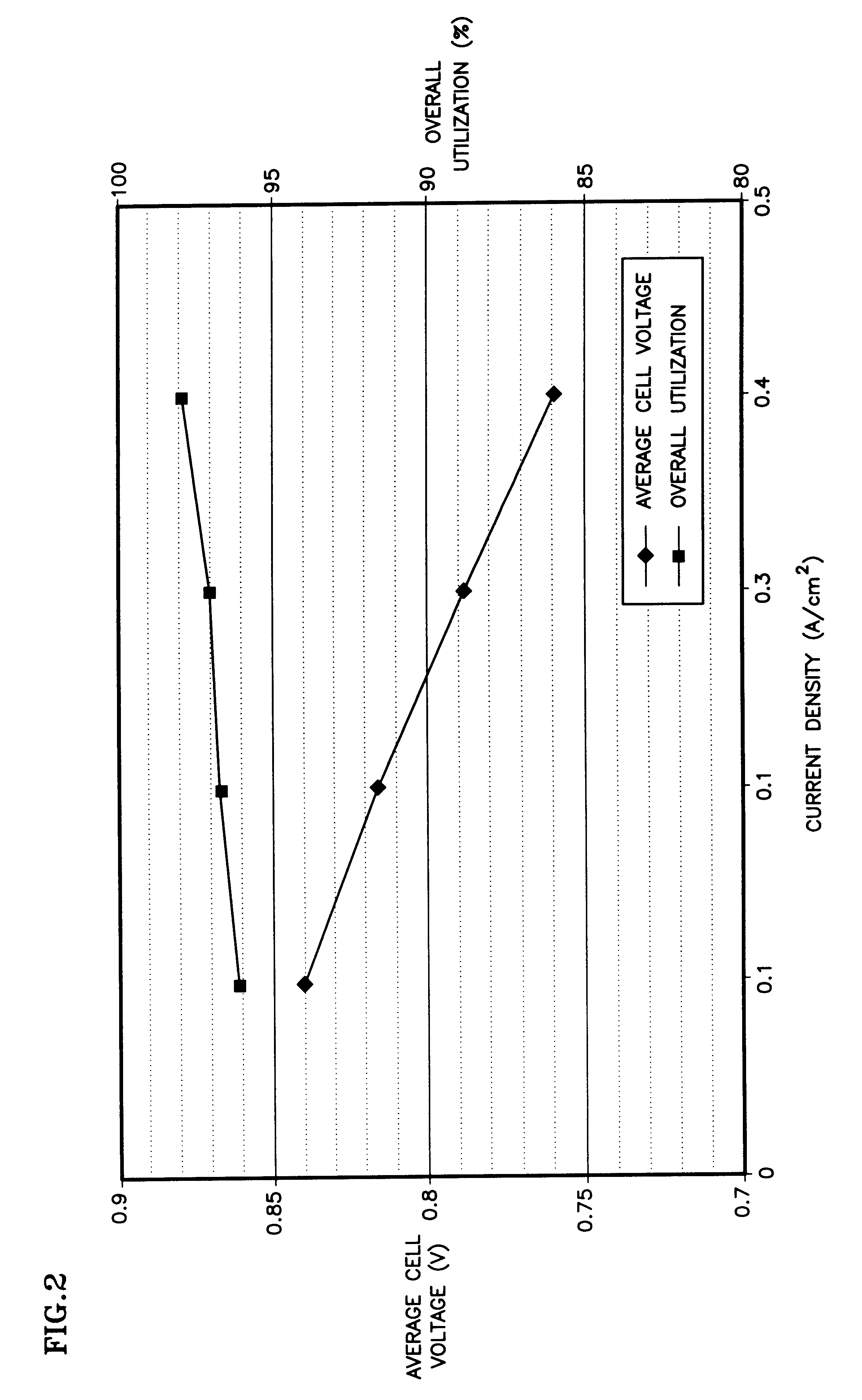
According further to the invention, the load of the fuel cells is monitored, and when operating at high or peak power, additional hydrogen may be provided to the anode flow field by virtue of venting the anode flow field either to ambient or to fuel effluent processing apparatus. At the increased reaction rate when generating high power, the proportional loss of hydrogen is less. Thus, when operating below high power levels, which is most of the time in a vehicle, a fuel cell having an unvented fuel reactant flow field will have a sufficiently high utilization of hydrogen, about 96% to 98%, to offset and exceed any loss of electrochemical efficiency which may result from the reduction in hydrogen partial pressure in the fuel flow field.

Problems solved by technology

Since all the fuel must be carried on board the vehicle, and since accessories that may enhance fuel cell performance must nonetheless be powered, electrically, by the fuel cell, thus reducing the overall power plant efficiency, the question of fuel cell efficiency becomes paramount.
It is known that fuel cell performance suffers significantly whenever fuel gas is not provided appropriately to the entire surface of the electrolyte.
However, the higher concentration of hydrogen, which typically may be over 90% at the inlet to the anode fuel flow field, drives the diffusion of the fuel through the membrane where it will react at the cathode with oxygen, thus reducing the efficiency of the electric power generation process.

Method used


Image

  • High fuel utilization in a fuel cell
  • High fuel utilization in a fuel cell
  • High fuel utilization in a fuel cell

Examples


Embodiment Construction

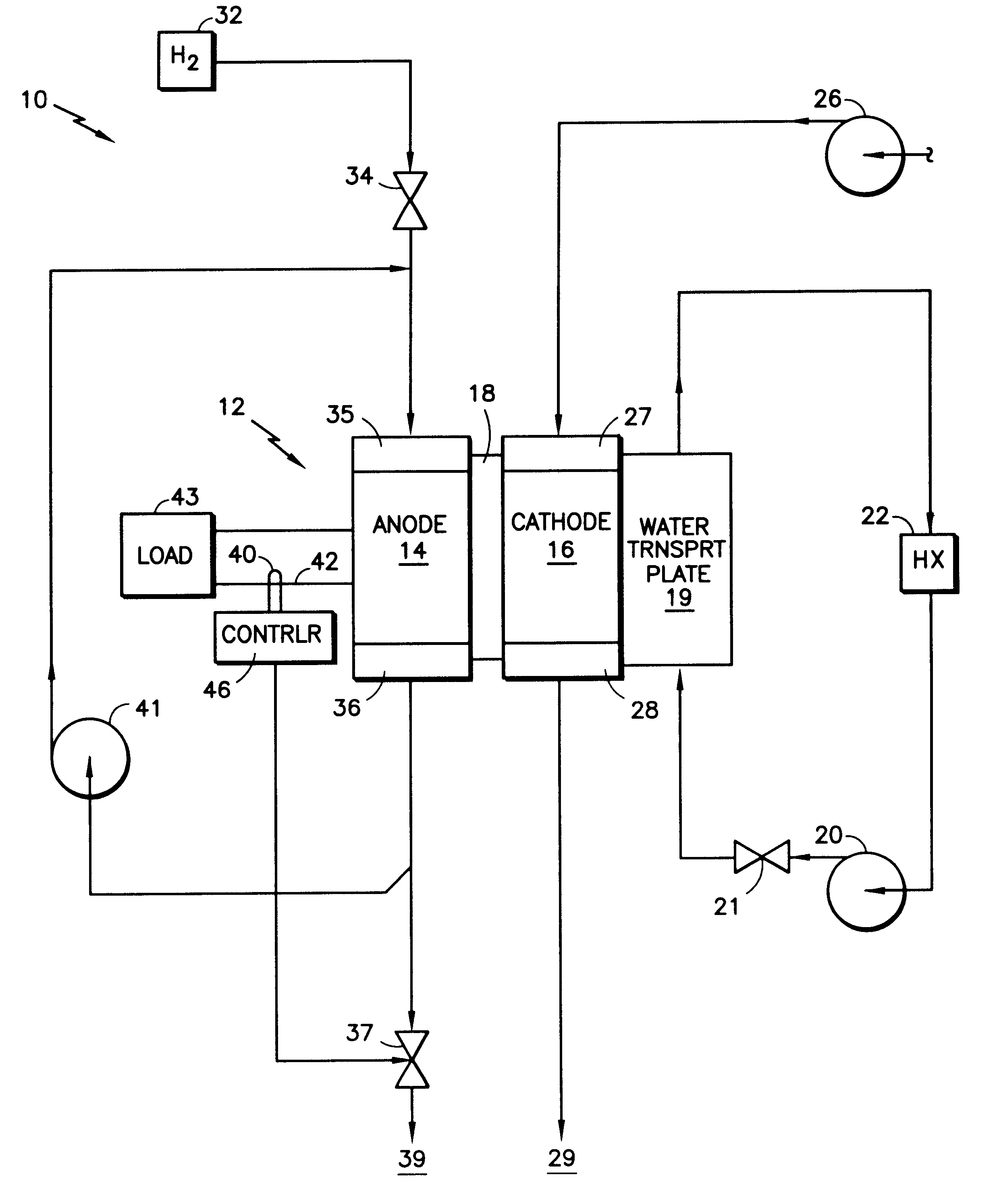
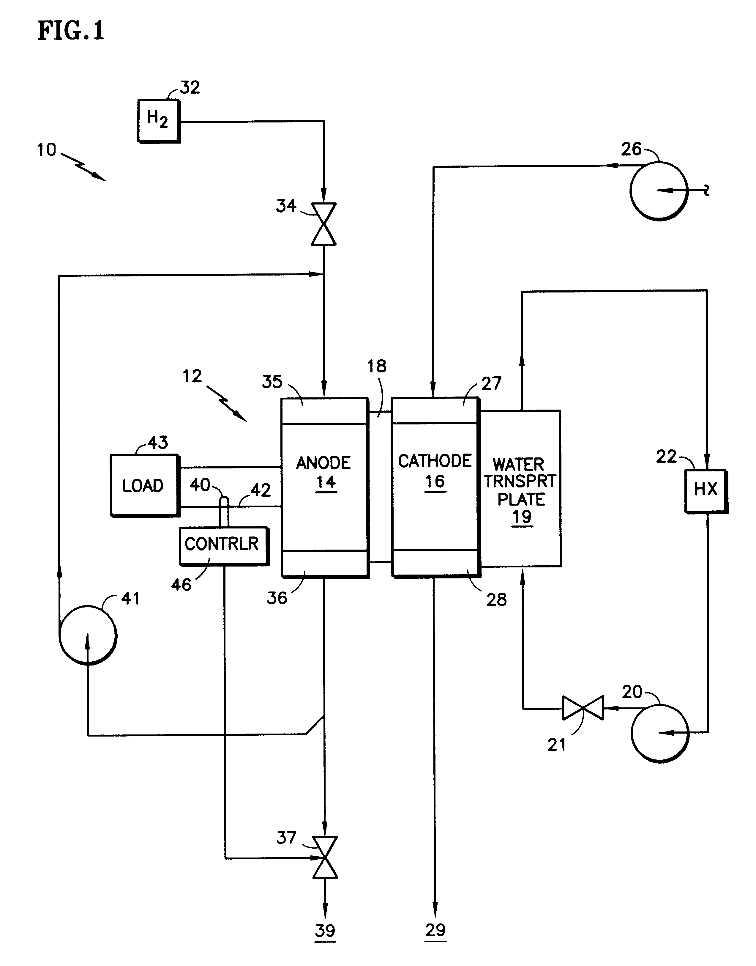
Referring to FIG. 1, a fuel cell power plant 10 includes a cell stack assembly 12 which comprises a plurality of individual fuel cells stacked together in contiguous relationship, although only a single cell is illustrated in FIG. 1. A fuel cell includes an anode electrode 14, a cathode electrode 16, and a polymer electrolyte membrane 18 disposed between the electrodes. Each electrode consists of a catalyst, a porous support plate and a reactant flow field as is well known. A water transport plate 19 (or coolant plate), adjacent to the cathode 16, is connected to a coolant control loop including a coolant pump 20, a coolant pressure valve 21, and a heat exchanger 22. There may be a heat exchange bypass and other water management apparatus, not shown, as disclosed in U.S. Pat. No. 5,503,944. The pump 20 and valve 21 will regulate both the pressure and the volume of flow through the water transport plate 19 and through, or around, the heat exchanger 22. Air is supplied by a blower 26 ...


PUM


Abstract

A PEM fuel cell (12) operating on substantially pure hydrogen (32) and air (26) has an exhaust flow control valve (37) at the exit of the anode fuel reactant flow field, said valve being normally closed during steady state low or medium power operation, so that the concentration of nitrogen in the fuel reactant flow fields, by diffusion across the membrane from the cathode, will approach the average concentration of nitrogen in the oxidant, thereby limiting the concentration of hydrogen to a corresponding low complementary amount, which reduces the diffusion of hydrogen across the membrane for consumption at the cathode, thereby increasing the efficiency of operation of the fuel cell. A current sensor (40) allows a controller (46) to open an exhaust flow control valve (37), thereby drawing much higher amounts of hydrogen into the fuel reactant flow field of the anode to support generation of power at high current densities without hydrogen starvation.

Description

This invention relates to causing a hydrogen / air fuel cell to utilize substantially all of the fuel reactant in the electrical production process through mitigation of diffusion of the fuel to the cathode side as a result of low fuel concentration on the anode side.Consideration is being given to utilization of fuel cells, particularly proton exchange membrane (PEM) fuel cells operating with hydrogen-rich fuel reactant gas and with air as the oxidant gas, for use in vehicles. Since all the fuel must be carried on board the vehicle, and since accessories that may enhance fuel cell performance must nonetheless be powered, electrically, by the fuel cell, thus reducing the overall power plant efficiency, the question of fuel cell efficiency becomes paramount. It is known that fuel cell performance suffers significantly whenever fuel gas is not provided appropriately to the entire surface of the electrolyte. Therefore, it has been a common practice in the prior art to provide excess fuel...

Claims


Application Information

Patent Timeline
IPC IPC(8): H01M8/04H01M8/10H01M8/06
CPCH01M8/04097H01M8/04231H01M8/04761H01M8/04589Y02E60/50H01M8/04753
Inventor REISER, CARL A.
Owner AUDI AG
Learn More