Voltage control sensor and control interface for radio frequency power regulation in a plasma reactor

a voltage control sensor and radio frequency power regulation technology, applied in plasma welding apparatus, plasma technique, manufacturing tools, etc., can solve the problems of variable losses, unpredictable, and unpredictable losses, and the actual power delivered may unexpectedly change the process ra

Inactive Publication Date: 2003-05-13
LAM RES CORP
View PDF2 Cites 32 Cited by
  • Summary
  • Abstract
  • Description
  • Claims
  • Application Information

AI Technical Summary

Problems solved by technology

Significant variance in actual power delivered may unexpectedly change the rate of the process.
Unfortunately, the match network 30 generates significant losses in the RF signal.
Furthermore, these losses are variable and, to a degree, unpredictable.
Therefore, simply supplying a predetermined RF signal power from the RF power source 28 does not ensure that a predictable and consistent RF signal will be delivered at the electrode 26.
However, using such clamps 32 to attach the workpiece 14 to the chuck 16 presents multiple problems.
For one, valuable surface area may be wasted on the workpiece due to its engagement with the clamps 32.
In addition, any such contact of clamps 32 to the workpiece 14 is undesirable due the risk of damage to the workpiece 14, and the generation of particles.
However, use of such an electrostatic chuck 36 renders a direct measurement of the D.C. bias at the workpiece impractical.
In addition, it would be difficult to maintain sensor accuracy and longevity in the plasma environment.
Correlating the D.C. voltage by measuring the power of the RF signal at the electrode 16 is also difficult and does not provide an accurate measurement of the D.C. sheath potential due, in part, to the capacitive coupling between the electrode and the workpiece.
For instance the RF delivery system is subject to losses such that process results may not be predictable and constant.
For example, the match network generates substantial power losses in the RF signal, these losses being variable and, to an extent, unpredictable.

Method used


Image

  • Voltage control sensor and control interface for radio frequency power regulation in a plasma reactor
  • Voltage control sensor and control interface for radio frequency power regulation in a plasma reactor
  • Voltage control sensor and control interface for radio frequency power regulation in a plasma reactor

Examples


Embodiment Construction

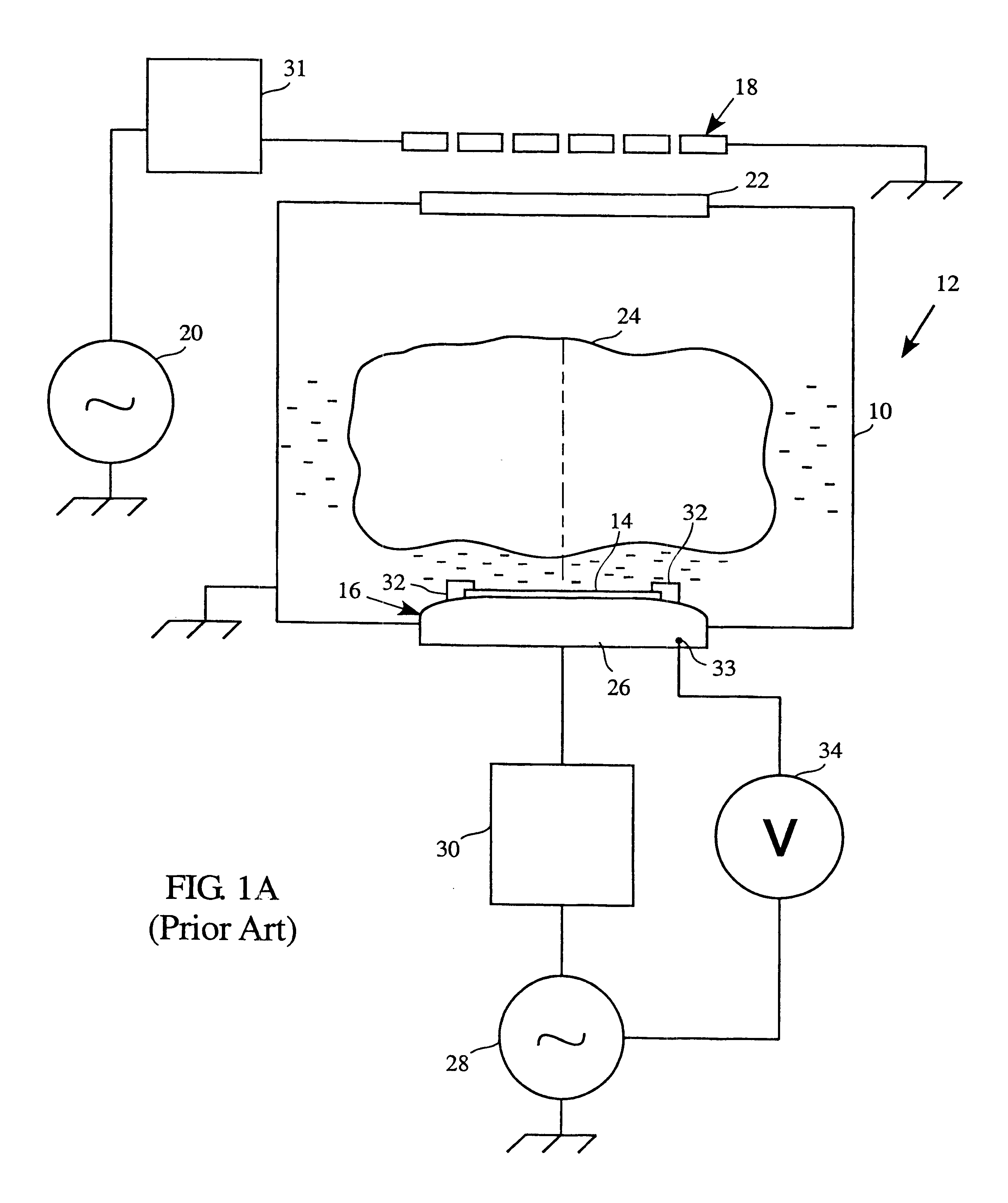
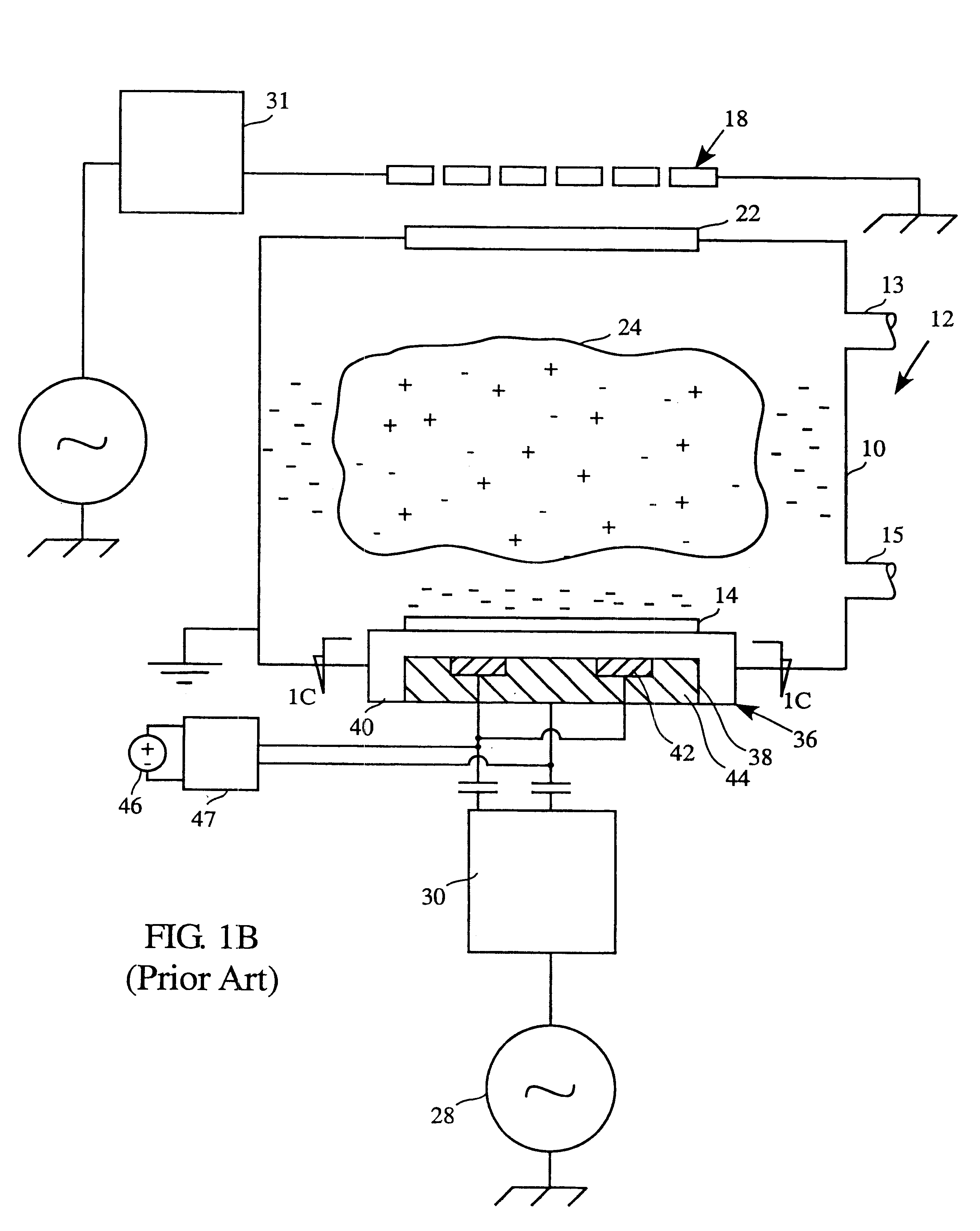
FIGS. 1A, 1B and 1C have been discussed with reference to the background art.

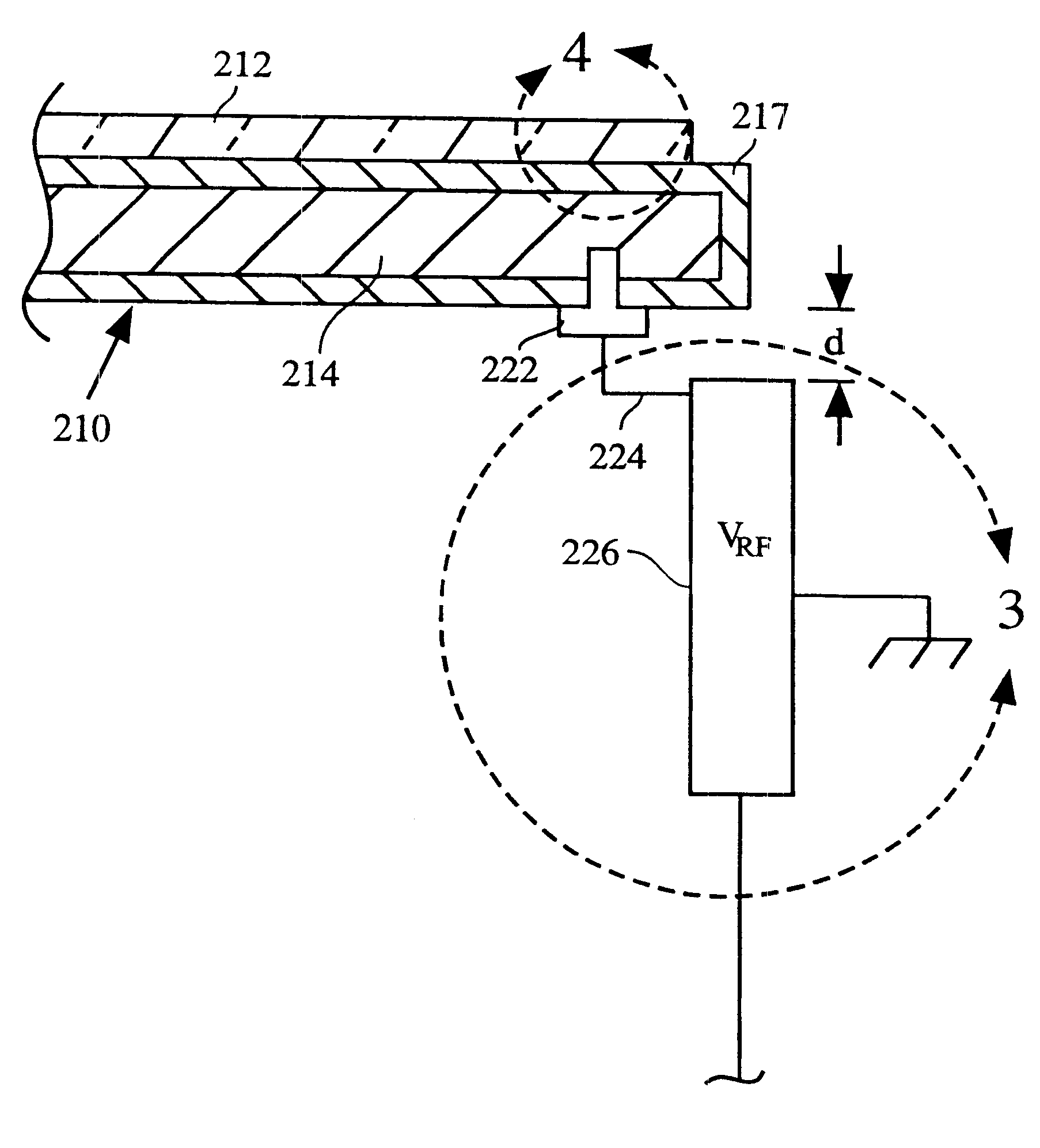
With reference to FIG. 2A, the present invention is embodied in a plasma reactor system, generally referred to as 200. The plasma reactor 200 includes a plasma chamber 202 and a Transformer Coupled Plasma (TCP) coil 204 disposed outside and above the plasma chamber 202. The plasma chamber 202 further includes a gas inlet 203 and a gas outlet 205. The TCP coil 204 is coupled with a plasma generation power source 206 which provides a plasma generating Radio Frequency (RF) signal. A match network 207 is included between the plasma generation power source 206 and the TCP coil 204. A ceramic window 208 located adjacent the TCP coil 204 in the upper wall of the chamber 202 allows efficient transmission of the plasma generating RF signal into the plasma chamber 202. An electrostatic chuck 210, located at the bottom of the chamber 202, supports a workpiece 212.

With continued reference to FIG. 2A, the electrostatic ...


PUM

PropertyMeasurementUnit
impedanceaaaaaaaaaa
impedanceaaaaaaaaaa
variable poweraaaaaaaaaa

Abstract

A plasma reactor system with controlled DC bias for manufacturing semiconductor wafers and the like. The reactor system includes a plasma chamber, a plasma generating coil and a chuck including a chuck electrode. The chuck supports a workpiece within the chamber. The plasma reactor system further includes a pair of generators, one of which supplies a radio frequency signal to the plasma generating coil. The second generator delivers a RF signal which to the chuck electrode and acts to control DC bias at the workpiece. Peak voltage sensor circuitry and set point signal circuitry controls the power output of the generator, and a matching network coupled between the generator and the first electrode matches the impedance of the RF signal with the load applied by the plasma. DC bias determines the energy with which plasma particles impact the surface of a workpiece and thereby determines the rate at which the process is performed. This DC bias forms at the surface of the workpiece upon generation of a plasma in the plasma chamber and is affected by the RF signal applied to the chuck electrode. Since power losses within the match network are variable and unpredictable, the peak voltage at the electrode can not be consistently maintained by simply applying a predetermined generator output. By monitoring the peak voltage at the electrode and generating a corresponding control signal to control the generator, a consistent DC bias and corresponding process rate can be maintained.

Description

1. Field of the InventionThe present invention relates to plasma processing systems and, more particularly, to methods and apparatus for controlling radio frequency delivery in a plasma reactor through monitoring and feedback of an electrical parameter, in particular a peak voltage.2. Background ArtIonized gas, or plasma, is commonly used during the processing and fabrication of semiconductor devices. For example, plasma can be used to etch or remove material from semiconductor integrated circuit wafers, and to sputter or deposit material onto semiconducting, conducting or insulating surfaces.With reference to FIG. 1A, creating a plasma for use in manufacturing or fabrication processes typically begins by introducing various process gases into a plasma chamber 10 of a plasma reactor, generally designated 12. These gases enter the chamber 10 through an inlet 13 and exit through an outlet 15. A workpiece 14, such as an integrated circuit wafer is disposed in the chamber 10 held upon a...

Claims


Application Information

Patent Timeline
Patent Type & Authority Patents(United States)
IPC IPC(8): H01J37/32H05H1/00B01J19/08C23C16/52H01L21/205H01L21/3065H05H1/46
CPCH01J37/32082H01J37/3299H01J37/32935H01J37/32192H01J37/32
Inventor BENJAMIN, NEILBALDWIN, SCOTTJAFARIAN-TEHRANI, SEYED JAFAR
Owner LAM RES CORP
Why Eureka
Try Eureka