Battery pack charging system and battery pack

a battery pack and charging system technology, applied in the field of charging systems, can solve the problems of shortening the service life, difficult to handle batteries, and danger of inflammation

Inactive Publication Date: 2003-05-13
MAKITA CORP
View PDF9 Cites 92 Cited by
  • Summary
  • Abstract
  • Description
  • Claims
  • Application Information

AI Technical Summary

Benefits of technology

In the charging system in accordance with the more preferred teaching of the present invention, when the charging device charges the first battery which can be charged at a constant current, such as a nickel-hydrogen battery, charging of the battery is conducted, while the current value is being adjusted so that the temperature follows the target temperature increase pattern. As a result, charging can be conducted within a short time so that the nickel-hydrogen battery demonstrating an intensive increase in temperature is not heated to a high temperature. Moreover, when the same charging device is used for charging the second battery which can be charged only at a potential no higher than the preset level, such as a lithium ion battery, charging is conducted, while the electric current is being adjusted so that the voltage follows the target voltage increase pattern. As a result, the lithium ion battery can be charged at a potential no higher than the preset level. Therefore, the first battery which can be charged at a constant current, such as a nickel-hydrogen battery, and a second battery which can be charged only at a potential no higher than the preset level, such as a lithium ion battery, can be charged with one charging device provided with no constant-voltage charging circuit.
In accordance with the more preferred teaching of the present invention, a detection unit detects the temperature of the first battery based on the potential of a resistor connected to a temperature detecting element incorporated in the first battery. As a result, the detection unit can accurately detect the temperature of the first battery based on the potential of the resistor and also the battery voltage of the second battery based on the potential corresponding to the battery voltage from the output unit of the second battery.

Problems solved by technology

Nickel-hydrogen batteries may have a capacity higher than that of nickel-cadmium batteries that have found wide application, but they generate a large amount of heat in charging, and when a high temperature is reached because of such heat generation, the electrodes or separators of the battery inner cell are degraded, shortening the service life and, therefore, making the batteries difficult to handle.
When a potential above the preset level was applied to the lithium ion batteries, there was even a danger of inflammation and the batteries were very difficult to handle.
However, it was predicted that since a potential exceeding the preset value cannot be applied to lithium ion batteries, as was mentioned above, and the lithium ion batteries have to be charged at a constant voltage, a constant-voltage charging circuit has to be added to make the charging possible which will increase the cost.

Method used


Image

  • Battery pack charging system and battery pack
  • Battery pack charging system and battery pack
  • Battery pack charging system and battery pack

Examples


first embodiment

The charging principle of the first embodiment will be described below with reference to FIG. 6. In FIG. 6, a battery temperature rise value is plotted against the ordinate and the charging time is plotted against the abscissa. Curve L in the figure represents the temperature rise values at charging completion corresponding to the charging time, those values being observed when charging was conducted so that the temperature rise value was constant. For example, when the electric current was controlled so that the battery temperature that initially was 20.degree. C. reached 53.degree. C. (temperature rise value of 33 deg), the charging time was 20 min, when the electric current was controlled so that the battery temperature reached 43.degree. C. (temperature rise value of 23 deg), the charging time was 30 min, and when the electric current was controlled so that the battery temperature reached 78.degree. C. (temperature rise value of 58 deg) the charging time was 10 min.

Thus, the tem...

second embodiment

Specific charging control in the charging device of the second embodiment will be described below with reference to FIG. 10.

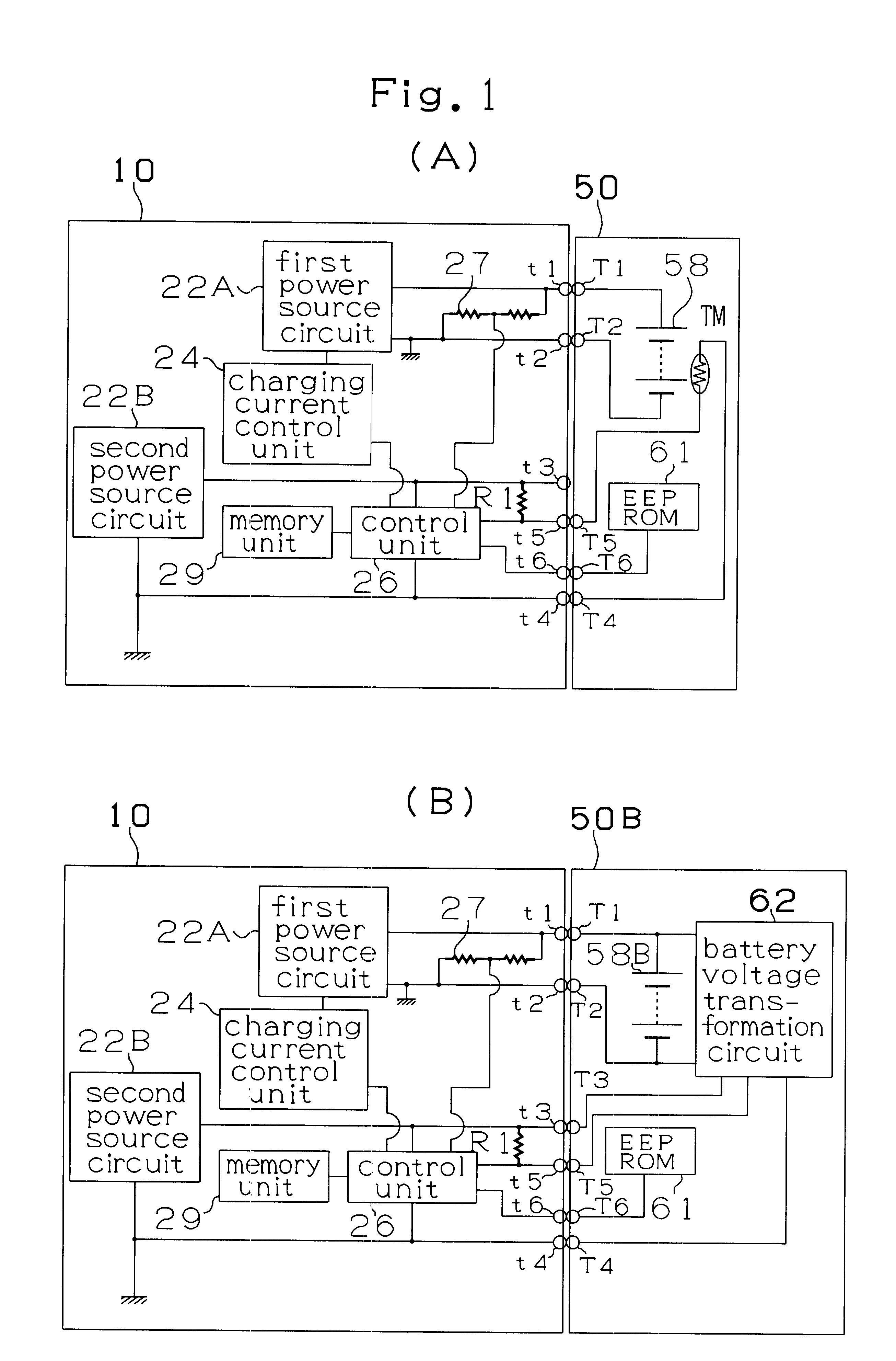
[Case when Nickel-Hydrogen Battery Pack 50 is Charged by the Charging Device]

First, the charging device reads the contents of EEPROM 61 of battery pack 50 (S12). Then, the read-out content is used to determine whether the batteries which are to be charged are in a nickel-hydrogen battery pack 50 or in a lithium ion battery pack 50B (S14). In case of lithium ion batteries (S14: Yes), the program proceeds to the below described charging of lithium ion batteries. On the other hand, in case of nickel-hydrogen batteries (S14: No), control unit 26 detects the temperature of battery pack 50 based on the voltage value determined by the voltage dividing resistance of thermistor TM and resistor R1 (S16). Then, the peak-like temperature rise pattern described above with reference to FIG. 7 is calculated based on data read from EEPROM 61 of nickel-hydrogen battery pack 50 ...


PUM

PropertyMeasurementUnit
constant voltageaaaaaaaaaa
voltageaaaaaaaaaa
temperatureaaaaaaaaaa

Abstract

Charging device 10 charges nickel-hydrogen batteries 58, while adjusting the current value so that the temperature follows the target temperature rise pattern. Therefore, nickel-hydrogen batteries that demonstrate a large temperature increase can be charged within a short time so that a high temperature is not attained. Furthermore, when lithium ion batteries 58 are charged, the current value is controlled so that the voltage follows the target voltage rise pattern. Therefore, lithium ion batteries can be charged at a potential no higher than the preset level.

Description

1. Field of the InventionThe present invention relates to a charging system for charging a battery and to a battery pack. More specifically, the present invention relates to a charging system for charging a first battery which can be charged at a constant current, such as a nickel-hydrogen battery, and a second battery which cannot be charged at a constant current and can be charged only at a potential below the preset level, such as a lithium ion battery, with the same charging device, and to a battery pack in which the second battery which cannot be charged at a constant current is charged by using a charging device for charging the first battery which can be charged at a constant current, such as a nickel-hydrogen battery.2. Discussion of the Prior ArtNickel-hydrogen batteries are presently used as high-performance batteries. Nickel-hydrogen batteries may have a capacity higher than that of nickel-cadmium batteries that have found wide application, but they generate a large amoun...

Claims


Application Information

Patent Timeline
Patent Type & Authority Patents(United States)
IPC IPC(8): H02J7/00H01M10/44H01M10/48H02J7/02H02J7/10
CPCH02J7/0045
Inventor SAKAKIBARA, KAZUYUKIFUKUMOTO, MASAAKI
Owner MAKITA CORP
Why Eureka
Try Eureka