Flexible tube, and method for manufacturing same

a flexible tube technology, applied in the field of flexible tubes, can solve the problems of inferior flexibility of crystalline polymer resin itself, the wall thickness of the flexible tube remains the same, and the prior art flexible tube still has a number of problems

Inactive Publication Date: 2003-05-20
FUJI PHOTO OPTICAL CO LTD
View PDF5 Cites 60 Cited by
  • Summary
  • Abstract
  • Description
  • Claims
  • Application Information

AI Technical Summary

Benefits of technology

It is another object of the present invention to provide a flexible tube which can be reduced in diameter, without sacrificing properties which are required for application to medical diagnostic or therapeutic instruments.
It is still another object of the present invention to provide a flexible tube of the sort as mentioned above, which can contribute to reduce the outside diameter of an endoscopic insertion instrument when applied as a biopsy channel of the insertion instrument.
The flexible tube according to the present invention can be advantageously used as a biopsy channel of an endoscopic insertion instrument.

Problems solved by technology

However, the crystalline polymer resin itself is inferior flexibility.
However, this prior art flexible tube still has a number of problems.
One problem relates to the wall thickness of the flexible tube.
The use of the outer layer, having a reinforcing layer sandwiched between urethane resin layers, makes reductions in wall thickness very difficult.
In addition, reductions in wall thickness are also difficult with regard to the inner layer which is formed by extrusion molding.
Thus, the prior art flexible tube has limits in reducing the wall thickness of the flexible tube as a whole.
However, the use of a helical metal wire winding as a reinforcing layer is insufficient in guaranteeing required shape retainability and strength of the biopsy channel particularly when a load is exerted in a twisting direction.
Further, the above-mentioned properties such as air tightness, water tightness, slipperiness, low friction coefficient, resistance to chemicals, feasibility of disinfection by washing and biotic safety are properties which are required of interior and exterior surfaces of a flexible tube, and do not necessarily have direct relation with the wall thickness.
For this reason, the flexible tube which is disclosed in Laid-Open Japanese Patent Specification H5-95892 is not necessarily suitable for use as a biopsy channel to be incorporated into an endoscopic insertion instrument, considering its non-smooth interior surface conditions.
As discussed above, in a case where the wall thickness of an inner layer of a flexible tube is reduced almost to an ultimate limit, it is very likely that repeated insertions of biopsy or surgical instruments can cause frictional wear or damages to certain localities of the inner layer and result in inward exposure of the outer layer through ruptured portions of the inner layer.
This of course detrimentally affects the feasibility of disinfection by washing and resistance to chemicals on the interior side of the flexible tube.
Therefore, in developing a flexible tube with interior surfaces of suitable properties for use as a biopsy channel on a medical endoscope, there have been limits to the reduction of wall thickness of an inner layer of the flexible tube, making it extremely difficult to reduce the diameter of the endoscopic biopsy channel.

Method used


Image

  • Flexible tube, and method for manufacturing same
  • Flexible tube, and method for manufacturing same
  • Flexible tube, and method for manufacturing same

Examples


Embodiment Construction

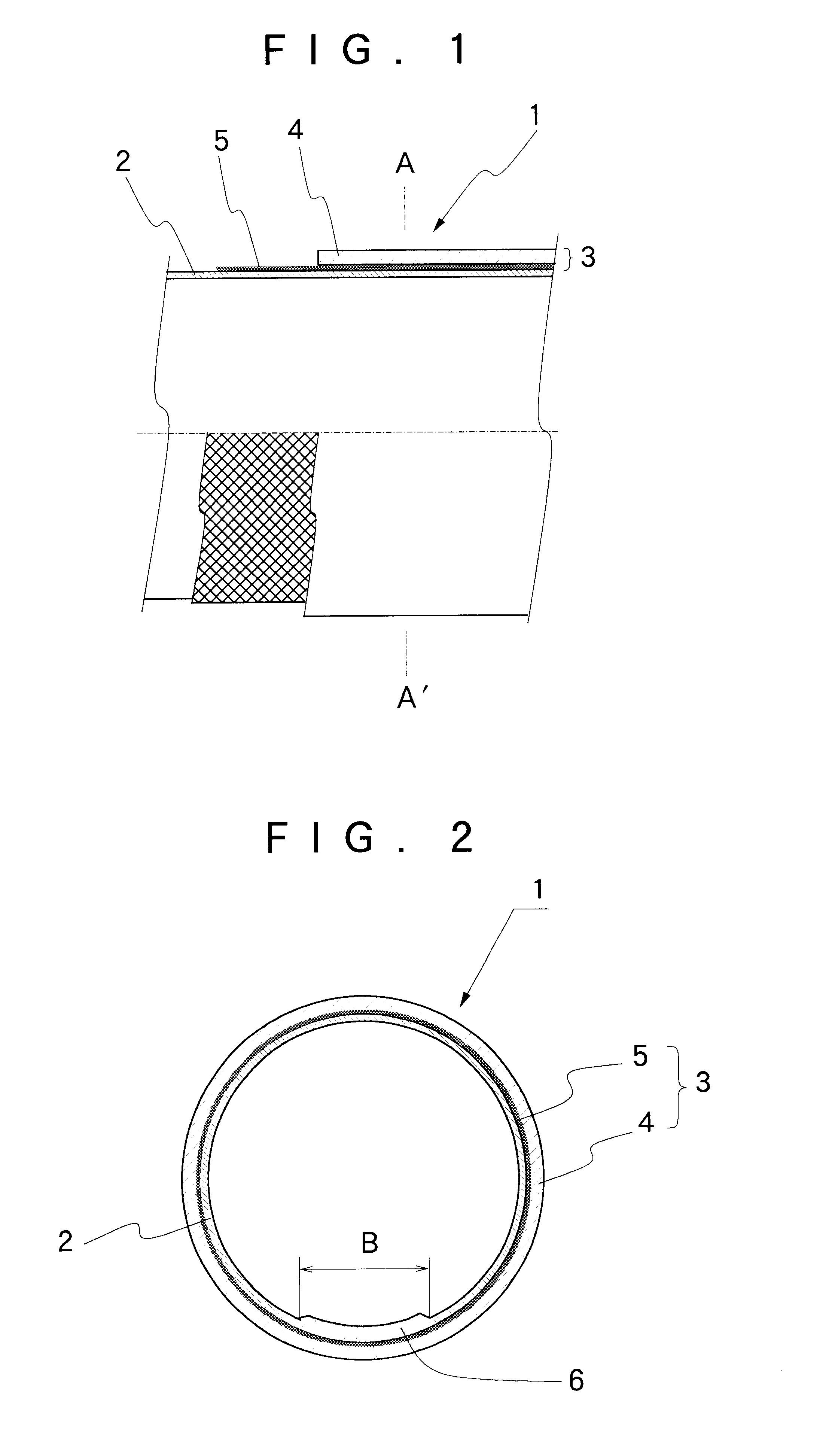
Hereafter, the present invention is described more particularly by way of its preferred embodiments shown in the accompanying drawings. Firstly, reference is had to FIG. 1 which shows the general layout of a flexible tube which constitutes an endoscopic biopsy channel, and to FIG. 2 which shows the flexible tube in a transverse section.

As clear from these figures, a flexible tube 1 which constitutes a biopsy channel in an endoscopic insertion instrument is composed of an inner layer 2 and an outer layer 3. The inner layer 2 is formed of a thin film tube of air tight and low friction coefficient material, preferably of tetrafluoroethylene resin (PTFE) or non-calcined hexafluoroethylene resin. On the other hand, the outer layer 3 is formed of a main tube body layer 4 and a reinforcing layer 5 which consists of metal mesh or metal knit fabric. The mesh 5 is directly laminated on the inner layer 2, and is formed by knitting or weaving hard metal fiber having spring action, for example, ...


PUM

PropertyMeasurementUnit
diametersaaaaaaaaaa
thicknessaaaaaaaaaa
diameteraaaaaaaaaa

Abstract

A flexible tube having a laminated multi-layer structure including an outer layer composed of a main tube body layer formed of thermoplastic synthetic resin in a predetermined thickness and a reinforcing layer provided on the inner side of the main tube body layer, and an inner layer formed of a thin film sheet of air tight and low friction material. The inner layer is formed by rolling an elongated strip of a thin film sheet into a tubular form such that opposite lateral sides of the thin film sheet are overlapped one on the other to provide a thick wall portion extending longitudinally of and at one angular position of the inner layer.

Description

1. Field of the ArtThis invention relates to a flexible tube which is particularly useful, for example, as a biopsy channel or guide tube to be incorporated into an endoscopic insertion instrument or as a catheter or the like, and a method for manufacturing such guide tubes.2. Prior ArtGenerally, endoscopes which are in use in medical fields are constituted by a manipulating head assembly to be gripped by an operator and an insertion instrument which is extended forward from the manipulating head assembly for insertion into a patient's body cavity. By way of properties, an endoscopic insertion instrument can be divided into three sections, i.e., a rigid tip end section which is provided at a fore distal end of the insertion instrument, an angle section which is connected to a proximal end of the rigid tip end section, and an elongated flexible body section which is connected between a proximal end of the angle section and the manipulating head assembly. Endoscopic observation means ...

Claims


Application Information

Patent Timeline
Patent Type & Authority Patents(United States)
IPC IPC(8): A61B1/012A61B1/018B29D23/00F16L11/08B29C53/56B29C53/68B29C53/50B29C53/00B29C53/38B29C61/00B29C47/02A61B1/00B29C48/08B29C48/09B29C48/10B29C48/151B29C48/21
CPCA61B1/018B29D23/001F16L11/085B29C47/065B29C47/0038B29C47/021B29C53/385B29C53/50B29C53/562B29C53/68B29C61/006B29C2793/009B29K2023/06B29K2027/12B29K2027/18B29K2075/00B29K2077/00B29K2105/0836B29K2305/00B29K2995/0049B29K2995/0067B29K2995/0073B29L2009/00B29L2023/007B29C47/0026B29C47/0064B29C47/0021B29C47/0023B29K2705/00B29C48/08B29C48/09B29C48/10B29C48/001B29C48/0021B29C48/151B29C48/21
Inventor KAMATA, KOUICHIAKIBA, HARUOKIMURA, MASANORIMURAKI, KOUICHI
Owner FUJI PHOTO OPTICAL CO LTD
Why Eureka
Try Eureka