Air conditioning apparatus for vehicle

a technology for air conditioning apparatus and vehicle, which is applied in the direction of vehicle cleaning, lighting and heating apparatus, machine operation mode, etc., can solve the problems of large loss in ventilation system, large loss in blower unit, and large pressure loss of ventilation system

Inactive Publication Date: 2003-05-27
DENSO CORP
View PDF10 Cites 40 Cited by
  • Summary
  • Abstract
  • Description
  • Claims
  • Application Information

AI Technical Summary

Problems solved by technology

However, in the conventional air conditioning apparatus, because cool air and warm air are always mixed in the air mixing chamber even when any one of the defroster opening portion, the foot opening portion and the face opening portion are opened, the pressure loss of the ventilation sys

Method used


Image

  • Air conditioning apparatus for vehicle
  • Air conditioning apparatus for vehicle
  • Air conditioning apparatus for vehicle

Examples


first embodiment

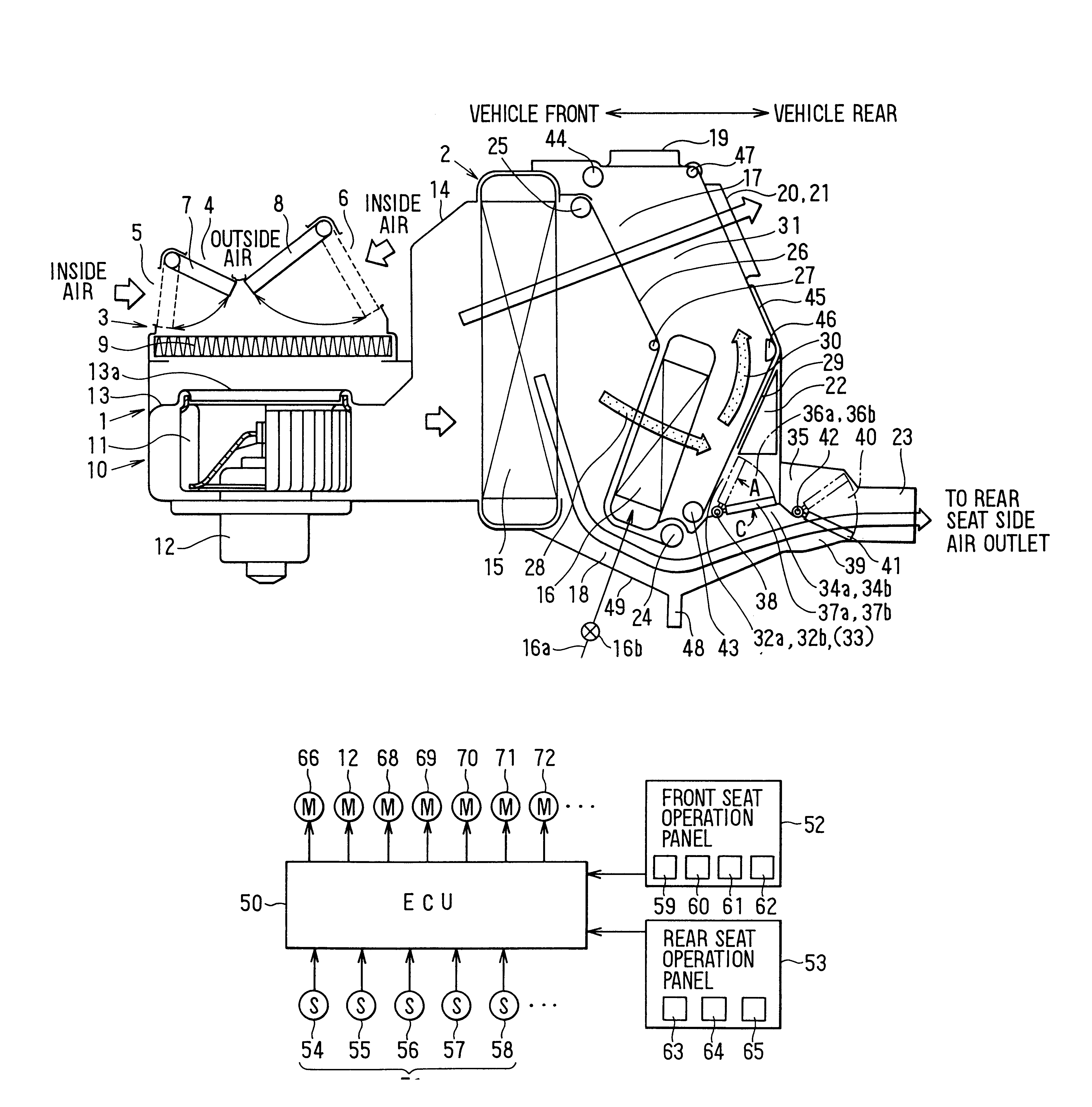
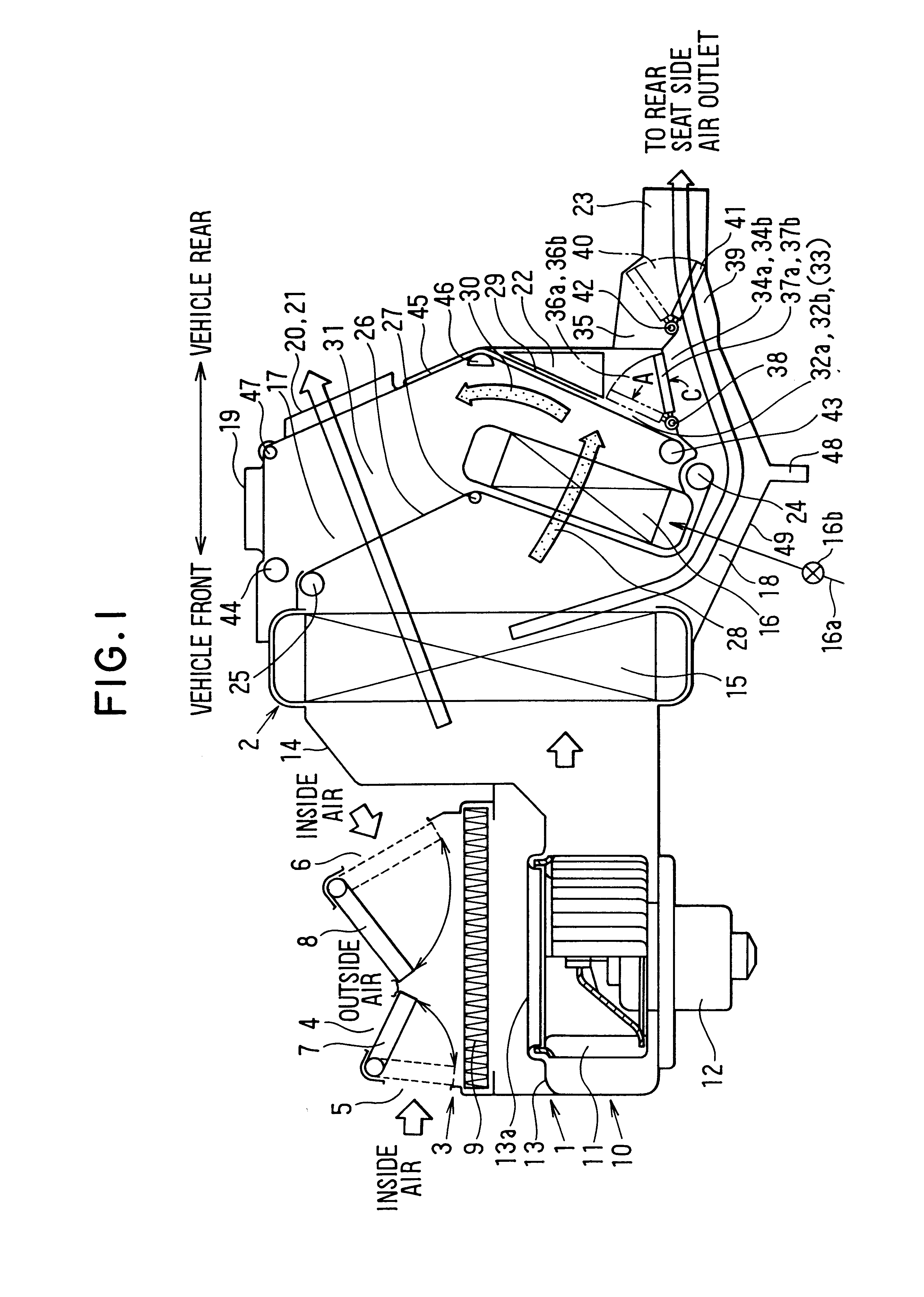
In the first embodiment, the air conditioning unit 2 is disposed at an approximate center portion in the left-right direction of the vehicle, under an instrument panel at a front side in the passenger compartment. The blower unit 1 is disposed at an offset position of the air conditioning unit 2 in the left-right direction of the vehicle. When the blower unit 1 is disposed in an engine compartment at an offset position relative to the air conditioning unit 2 in the left-right direction of the vehicle, the blower unit 1 can be disposed at the front side of the air conditioning unit 2 as shown in FIG. 1.

As shown in FIG. 1, the blower unit 1 has an inside / outside air switching box 3 at an upper side thereof. The inside / outside air switching box 3 includes an outside air introduction port 4 for introducing outside air (i.e., air outside the passenger compartment), inside air introduction Ad ports 5, 6 for introducing inside air (i.e., air inside the passenger compartment), and inside / ou...

second embodiment

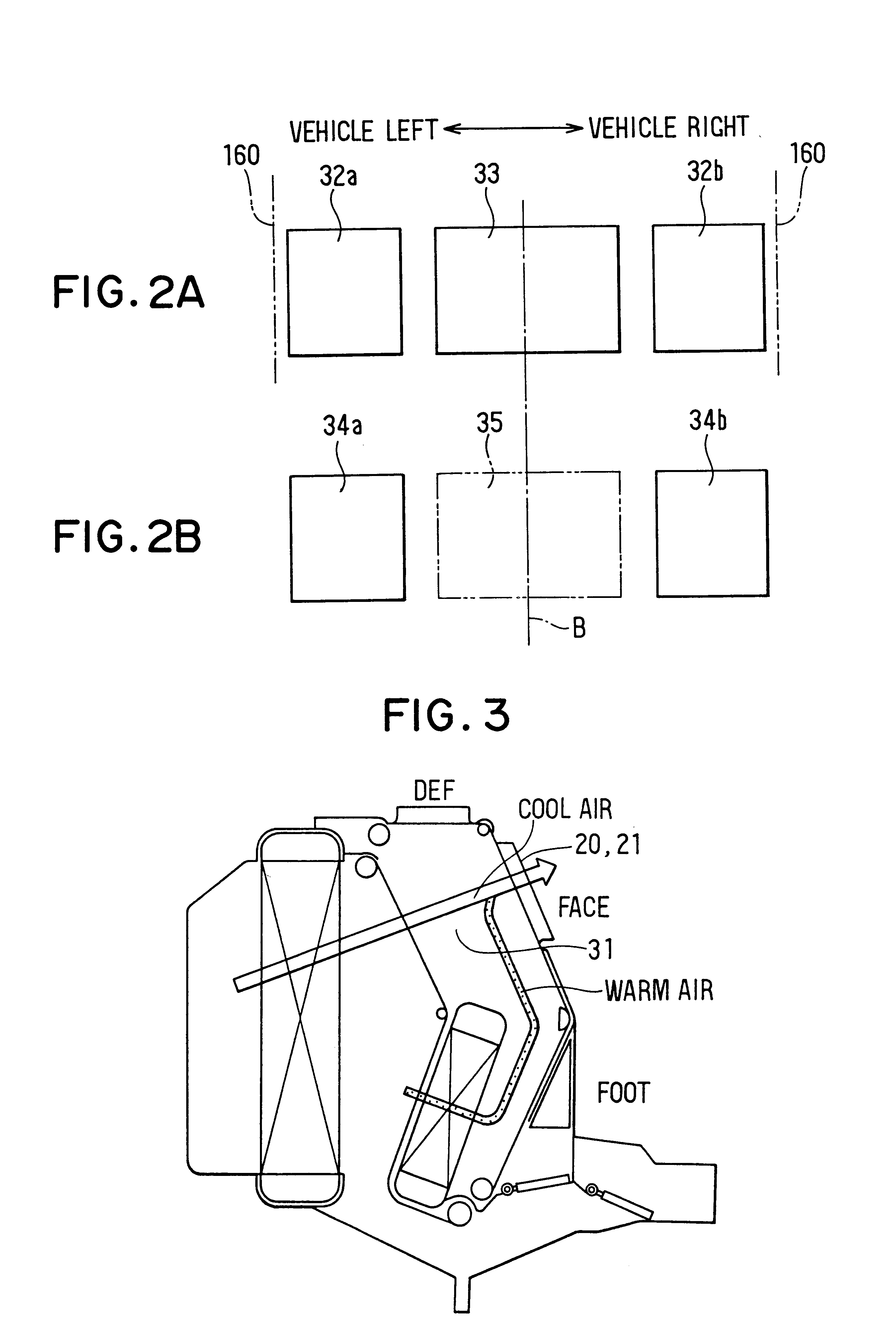
even when the maximum cooling mode is set at the front seat side in the passenger compartment during the face mode, the temperature of air to be blown toward the rear seat side in the passenger compartment can be controlled, because the air mixing film member 26 has supplementary opening portion 26b except of the main opening portions 26a as shown in FIG. 12.

Each supplementary opening portion 26b is provided at a side of the first driving shaft 24 to have a predetermined opening degree which is greatly smaller than that of a main opening portion 26a.

Next, the operation of the air conditioning apparatus according to the second embodiment will be now described. Here, only different operation portions different from those in the first embodiment are described.

When the maximum cooling mode is set at the front seat side in the passenger compartment during the face mode and the maximum cooling mode is also set at the rear seat side in the passenger compartment, the air mixing film member ...


PUM


Abstract

In an air conditioning apparatus for a vehicle, a first cool air bypass passage is provided at an upper side of a heater core, and a second cool air bypass passage is provided at a lower side of the heater core. Cool air from the first cool air bypass passage and warm air having passed through the heater core are mixed in a first air mixing chamber, and a ratio between an amount of cool air and an amount of warm air is adjusted by an air mixing film member. Further, cool air from the second cool air bypass passage and warm air from the heater core are mixed in a second air mixing chamber, a ratio between an amount of cool air and an amount of warm air is adjusted by an air mixing door, and the second air mixing chamber is provided at an immediately downstream air side of the heater core. Thus, in the air conditioning apparatus, a pressure loss in a ventilation system can be reduced.

Description

1. Field of the InventionThe present invention relates to an air conditioning apparatus for a vehicle, which controls a temperature of air blown toward a passenger compartment by adjusting a ratio between an amount of cool air and an amount of warm air, while decreasing a pressure loss in a ventilation system.2. Description of Related ArtIn a conventional air conditioning apparatus, an air conditioning unit including an evaporator, a heater core and an air outlet mode selecting mechanism is disposed in a front portion of a passenger compartment at an approximate center position in a left-right direction of the vehicle, and a blower unit for blowing air toward the air conditioning unit is disposed at an offset position of the air conditioning unit in the left-right direction. Warm air having passed through the heater core and cool air bypassing the heater core are mixed in an air mixing chamber, and the ratio between the amount of warm air and the amount of cool air is adjusted by an...

Claims


Application Information

Patent Timeline
IPC IPC(8): B60H1/00
CPCB60H1/00064B60H1/00692B60H2001/00164Y10S251/901B60H2001/00192B60H2001/002B60H2001/00728B60H2001/00171
Inventor UEMURA, YUKIOSHIKATA, KAZUSHINATSUME, TAKUYASUGI, HIKARU
Owner DENSO CORP
Why Eureka
Try Eureka