
Protection device for dual stage power supply

a protection device and power supply technology, applied in the direction of manufacturing tools, welding equipment, arc welding equipment, etc., can solve the problems of rapid temperature increase, rapid temperature increase, and rapid trip of the associated thermostat, and achieve the effect of not expensive, easy to manufacture, and positive in operation

Inactive Publication Date: 2003-05-27
LINCOLN GLOBAL INC
View PDF5 Cites 21 Cited by
  • Summary
  • Abstract
  • Description
  • Claims
  • Application Information

AI Technical Summary

Benefits of technology

Yet another object of the present invention is the provision of a protection device, as defined above, which protection device is easy to manufacture, can be used, or retrofilled on existing power supplies, is positive in operation and not expensive.

Problems solved by technology

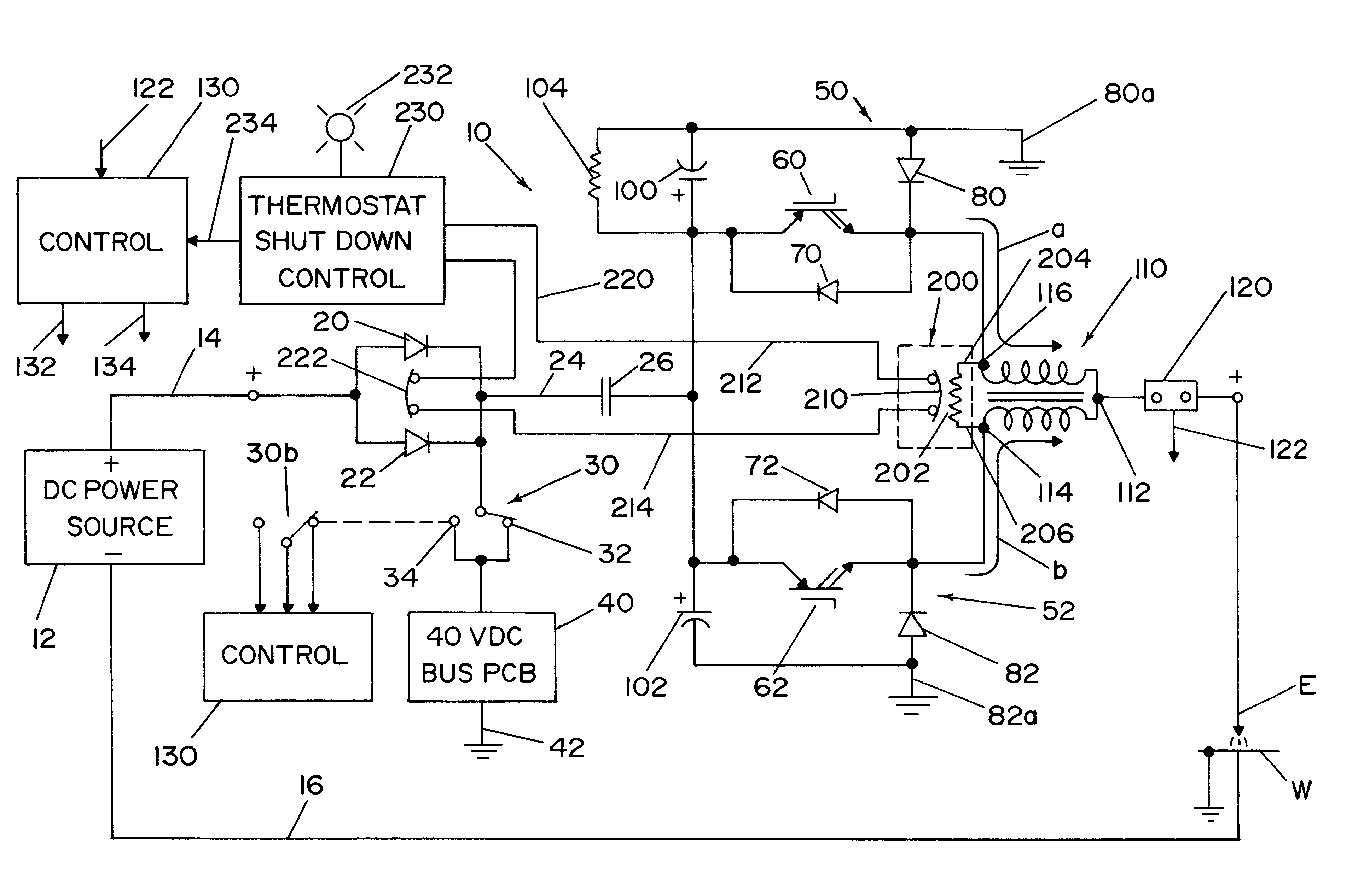
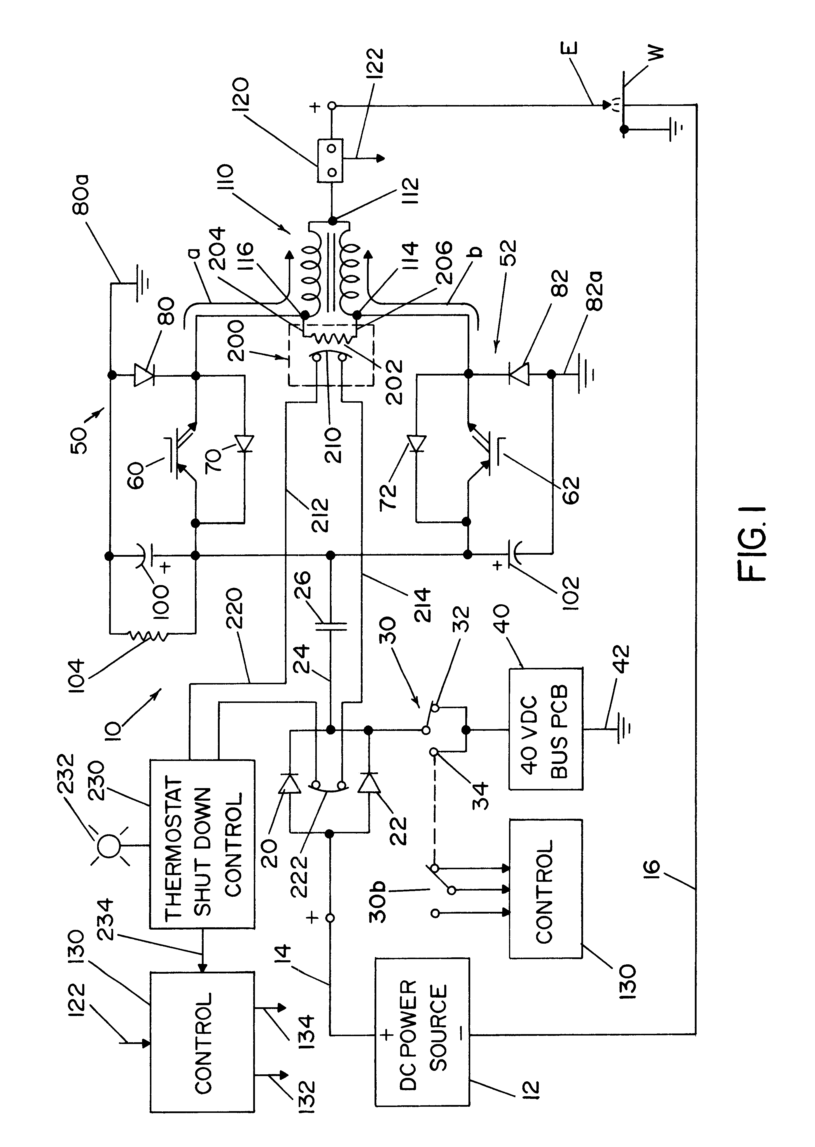
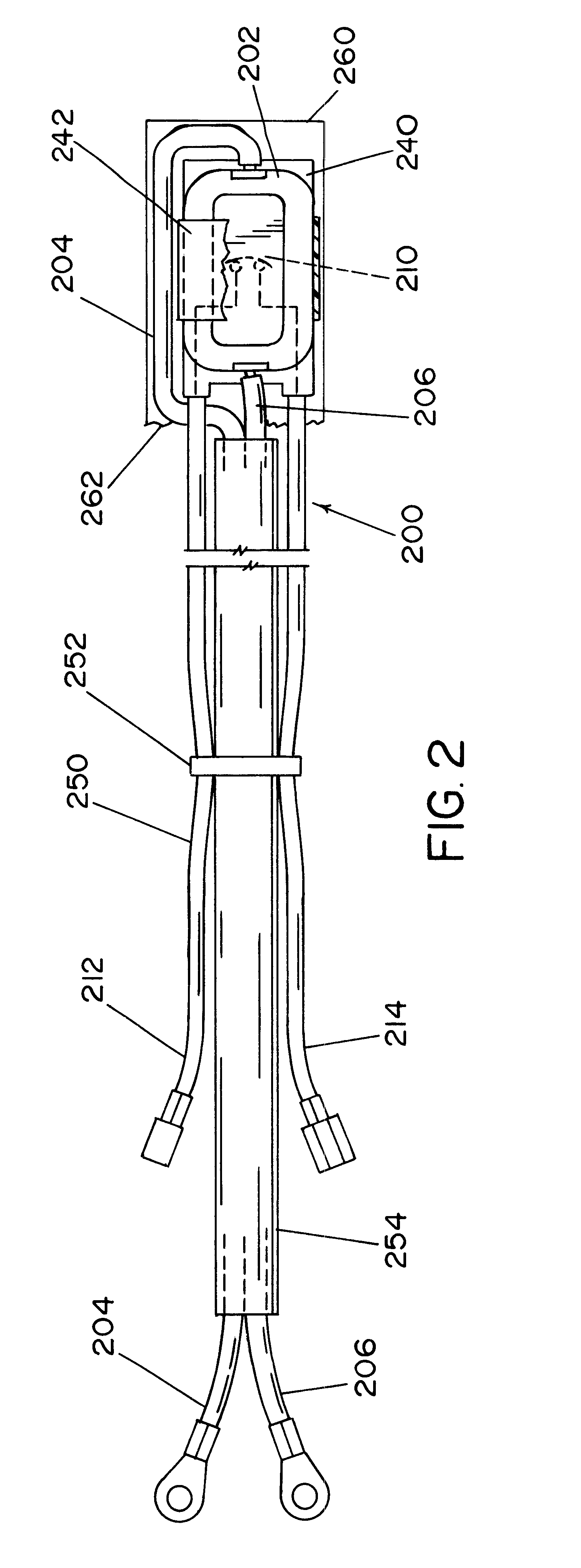
Thus, by merely adding a resistance that heats up rapidly between two substantially identical voltage points on the parallel power supply paths, the temperature of the resistor increases rapidly with critical imbalances and rapidly trips the thermostat to either provide a warning signal, deactivate the power supply or perform both of these functions.
Thus, typical operating voltage differences between the two ends of the appropriately selected power resistor will not cause the thermostat to trip in the highest operating ambient temperature, but voltage differences due to critical imbalance conditions causes rapid temperature increase and fast trip of the associated thermostat.
It has been found that in a complete imbalance with one stage inactive, the IGBT switches must be deactivated at a case temperature less than 125.degree. C.
Thus, the protection device switches within a short period of time and before the actual switch of the operating stage of the power supply is overheated.
However, when operated at lower voltage imbalance there is a minimum preheating of the thermostat.

Method used


Image

  • Protection device for dual stage power supply
  • Protection device for dual stage power supply
  • Protection device for dual stage power supply

Examples


Embodiment Construction

Referring now to the drawings, wherein the showings are for the purpose of illustrating a preferred embodiment of the invention and not for the purpose of limiting same, a dual stage chopper or power supply 10 is schematically illustrated as including a DC power source 12 with a positive lead 14 and a negative lead 16. Power supply 10 is a dual stage power supply for controlling a current through electrode E and workpiece W for electric arc welding or plasma cutting. The schematically illustrated power supply includes input diodes 20, 22 for a first positive lead 24 connected to the power supply by contactor 26. The contactor is selectively connected to activate the power supply with input filter capacitors 100, 102. Lead 24 is also directed to a center off DPDT switch 30 having a constant voltage on position or contact 32 and a constant current on position or contact 34 for activating the control power supply PCB 40 grounded at lead 42. The second pole 30b of switch 30 connects to ...


PUM

PropertyMeasurementUnit
Angleaaaaaaaaaa
Temperatureaaaaaaaaaa
Poweraaaaaaaaaa

Abstract

A protection device for use on a dual stage power supply for passing a current from first and second paths in unison across an electrode and a workpiece of an electric arc welder. The device includes a resistor connected between generally identical voltage points in the first and second paths, whereby current flows through the resistor based upon the difference in the voltage of the points, a thermostat mounted adjacent the resistor with the thermostat having a known temperature at which the thermostat is tripped and a circuit to provide a signal when said thermostat is tripped to the signal can shut down the power supply until it is reset.

Description

The present invention relates to the art of electric arc welding and more particularly to a protection device for a dual stage power supply used in electric arc welding.BACKGROUND OF INVENTIONIn electric arc welding and plasma cutting (collectively referred to as "electric arc welding") dual stage power supplies, such as a dual chopper, are often used to divide the power requirements for the welding operation into two parallel stages. In this manner, a chopper type power supply can provide twice as much electric energy to the welding or plasma cutting operation. The advantage of these parallel choppers are low cost and easy feedback control. However, dual choppers and other dual stage power supplies sometimes create a critical imbalance of the two current paths sharing the output current. The typical causes of this unbalance is poor connections, loss of the switching gate drive in one of the stages, or a failed stage. During such extreme imbalance conditions, one stage of a dual cho...

Claims


Application Information

Patent Timeline
IPC IPC(8): B23K9/10
CPCB23K9/1043B23K9/10
Inventor SAMODELL, RALPH M.
Owner LINCOLN GLOBAL INC
Learn More