Method and machine for producing multiaxial fibrous webs

a multi-axial, fiber-based technology, applied in the direction of knitting machines, ornamental textile articles, flat warp knitting machines, etc., can solve the problems of reducing the mechanical properties of composite materials prepared from such multi-axial sheets, reducing the cost of making such sheets, and limiting the use of that method

Inactive Publication Date: 2003-07-01
HEXCEL FABRICS +1
View PDF7 Cites 169 Cited by
  • Summary
  • Abstract
  • Description
  • Claims
  • Application Information

AI Technical Summary

Benefits of technology

An object of the invention is to propose a novel method of making multiaxial fiber sheets, in particular to enable the cost of making such sheets to be reduced, so as to cause multiaxial sheets made with fibers that have the reputation of being expensive, such as carbon fibers, to be more attractive.
In another variant, the successive segments of the transverse sheet can be placed not adjacent to one another, but with partial overlap (FIG. 15). The degree of overlap is adjusted by adjusting the speed of the conveyor 44 between two successive transverse sheet segments being brought into position. Such partial overlap makes it possible to avoid difficulties that can be encountered when placing transverse sheet segments edge to edge. Under such circumstances, lightweight transverse sheets are used as can be obtained after being spread as shown in FIG. 5.

Problems solved by technology

This inevitably results in undulations being formed which, when a plurality of sheets are superposed and pressed against one another, can cause fibers to be crushed and broken, thereby creating discontinuities.
That degrades the multiaxial sheets made in that way and consequently degrades the mechanical properties of the composite material parts prepared from such multiaxial sheets.
However it is necessary for the material of the bonding fibers to be compatible with the nature of the matrix of the composite material, which greatly limits the use of that method.
In that case also, the need for compatibility between the binder and the matrix limits applications of the method.
Furthermore, no means is described to enable the threads to be placed parallel to one another, and it will readily be understood that making wide sheets on an industrial scale gives rise to real practical difficulties.
Finally, the resulting sheet is not free from undulations resulting from the threads being placed side by side.
Nevertheless, multiaxial sheets are not made by superposing those unidirectional sheets.
Nevertheless, that gives rise to openings being present in the multiaxial sheet, which openings produce surface discontinuities.
With that technique it is not possible to have reinforcing threads in the longitudinal direction of the multiaxial sheet; unfortunately, it is often necessary to place reinforcing elements in that main direction.
Finally, it will be observed that that technique does not make a very high production speed possible given the time required for forming each unidirectional sheet.
Unfortunately, the wider the transverse sheets, the larger the marginal zones, and the larger the losses of material due to their being eliminated, and it is also more difficult to turn the sheets on the spikes.
This greatly limits the width that can be used for the transverse sheets.
In addition, the above-mentioned drawback of possible irregularity in the multiaxial sheet is also to be found, in particular due to the formation of holes because of the tensions that it is necessary to apply to the elements of the transverse sheets in order to hold them parallel during laying.
In addition to making it impossible to preserve a smooth surface state, this high stitch density affects the flexibility of the multiaxial sheet and limits its deformability in use, e.g. by draping.
Reinforcing elements are indeed provided that extend in the main direction (0.degree.), but the resulting multiaxial sheet is not symmetrical between its faces.
It should also be observed that a drawback common to those techniques using threads for forming unidirectional sheets lies in obtaining multiaxial sheets which firstly present surface roughness due to the threads, and secondly cannot be as thin as it is sometimes desired.
It should also be observed that the above-mentioned known techniques all suffer from a drawback which lies in the relatively high cost of multiaxial fiber sheets when they are made using carbon fibers.

Method used


Image

  • Method and machine for producing multiaxial fibrous webs
  • Method and machine for producing multiaxial fibrous webs
  • Method and machine for producing multiaxial fibrous webs

Examples


example 1

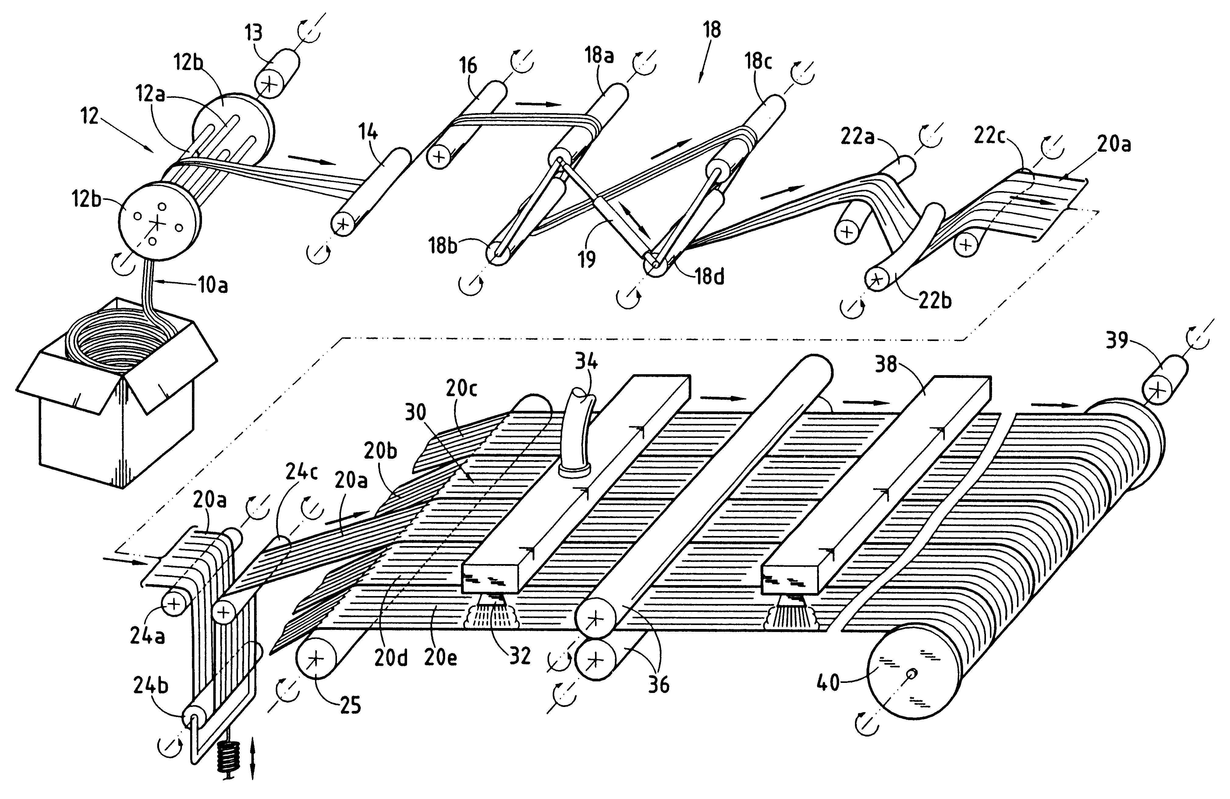
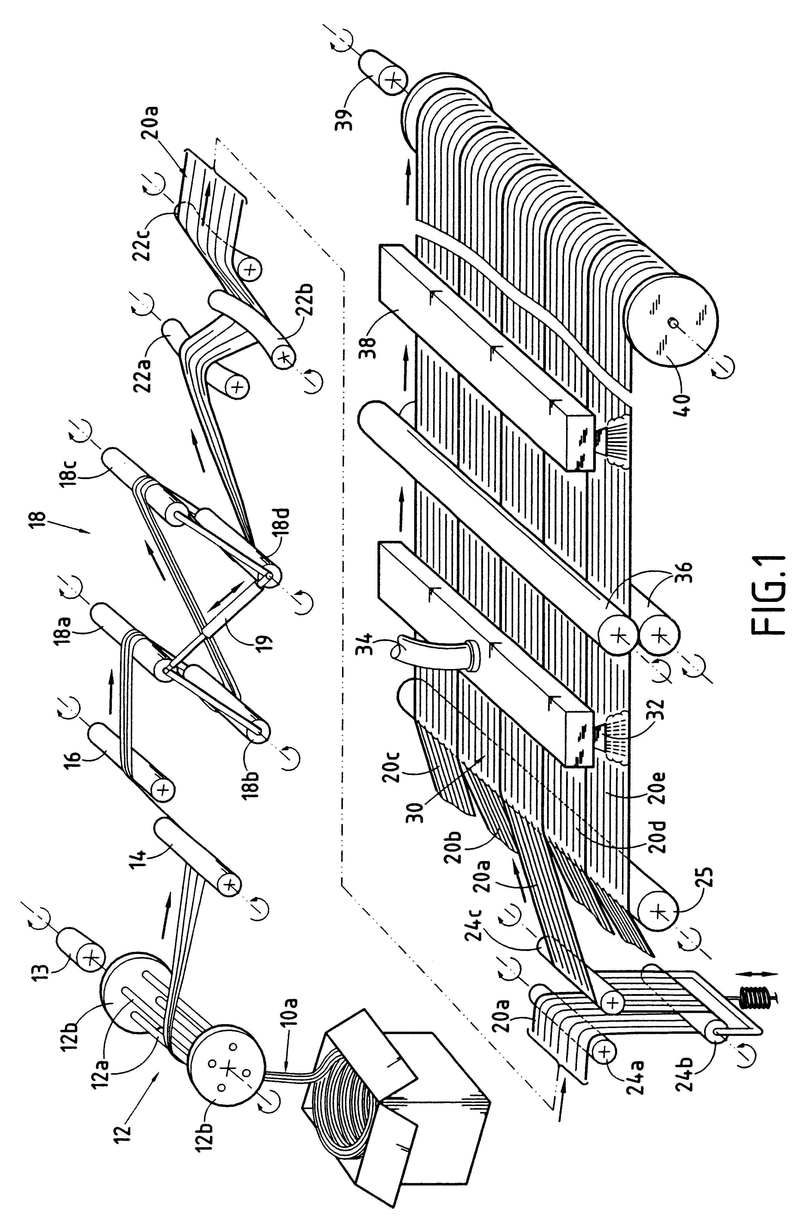
A tow of high-strength carbon fibers constituted by 480,000 continuous filaments (480 K) weighing 30,000 tex, having breaking strength in traction of 3600 MPa and a modulus of 250 GPa was spread over a width of 150 mm by means of an installation similar to that of FIG. 1. The spread tow was subjected to a stretching and bursting operation during which the continuous filaments were transformed into discontinuous filaments, the majority of which were of a length lying in the range 25 mm to 170 mm. During bursting, the spread tow was subjected to stretching by a factor of 2 and its weight (per unit area) was reduced, giving a unidirectional sheet having a width of 150 mm and a weight of 110 g / m.sup.2.

The sheet was fixed by disorienting the fibers slightly, the great majority of them remaining parallel to the sheet direction. The disorientation was performed by subjecting the sheet situated over a metal plate to a jet of water under a pressure of at least 100 bars.

The resulting sheet wa...

example 2

The two-axis sheet of Example 1 was fixed not by needling, but by stitching using a zigzag knit stitch parallel to the longitudinal direction. The knitting thread was a 150 dtex cotton thread having two strands. A two-axis sheet was obtained that was quite capable of being handled.

example 3

The tow of Example 1 as spread and fixed by a jet of water after stretching and bursting was enlarged by being passed over curved bars to increase its width from 80 mm to 120 mm. Two similar unidirectional sheets obtained in this way were laid at +45.degree. and -45.degree., as in Example 1, but with 50% overlap between successively-laid segments of sheet. The two-axis sheet was fixed by needling, as in Example 1. A two-axis sheet was obtained weighing 530 g / m.sup.2 and that was quite capable of being handled.


PUM

PropertyMeasurementUnit
widthaaaaaaaaaa
widthaaaaaaaaaa
anglesaaaaaaaaaa

Abstract

A plurality of unidirectional sheets (30a, 30b, 30c) are superposed in different directions and they are bonded together. At least one of the unidirectional sheets is made by spreading a tow so as to obtain uniform thickness, width not less than 5 cm, and a weight of no more than 300 g / m2, cohesion being imparted to the sheet so as to enable it to be handled prior to being superposed with other sheets. Advantageously, the unidirectional sheets are made of carbon fibers and are obtained by spreading out large tows.

Description

The invention relates to making fiber sheets, and more particularly multiaxial sheets formed by superposing and linking together a plurality of unidirectional fiber sheets disposed in different directions.A field of application of the invention lies in making multiaxial fiber sheets for forming reinforcing plies for preparing composite material parts. The intended materials are particularly those constituted by fiber reinforcement which can be organic or inorganic, or precursors therefor such as fibers of polymer, glass, carbon, ceramic, para-aramid, . . . , which reinforcement is densified by an organic matrix, e.g. a resin, or an inorganic matrix, e.g. glass, carbon, or ceramic.STATE OF THE ARTIt has been known for a long time to make multiaxial fiber sheets by superposing unidirectional sheets, i.e. made up of threads or fibers that are oriented essentially in a single direction, the unidirectional sheets being superposed in different directions.A common technique consists initia...

Claims


Application Information

Patent Timeline
Patent Type & Authority Patents(United States)
IPC IPC(8): B32B5/22B32B5/26B29C70/20B29C70/10D04H3/04D04H13/00D04H3/02D04H3/05D04H3/08B29C70/06B29C70/16B65H59/10D04H3/002D04H3/004D04H3/10D04H3/105D04H3/11
CPCB29C70/202B65H59/10D04H3/002D04H3/004D04H3/04D04H3/05D04H3/10D04H3/105D04H3/11D04H13/00D04H13/003D04B21/165D02J1/18B32B5/26Y10T156/1085B65H2701/314B65H2701/38D04H3/08D10B2505/02Y10T156/1322Y10T428/24322Y10T428/24033Y10T156/1052Y10T428/298Y10T428/24132Y10T428/2913Y10T428/24058B29C70/24B29C70/38B29C70/50B29C70/545B29C2793/0027B29C2793/0081D04B23/10D10B2403/02412Y10T428/249924B32B5/12B32B2262/0269B32B2262/101B32B2262/105B32B2262/106B32B2305/08
Inventor BOMPARD, BRUNOOLRY, PIERREDUVAL, RENAUDBRUYERE, ALAINCOUPE, DOMINIQUEAUCAGNE, JEAN
Owner HEXCEL FABRICS
Why Eureka
Try Eureka