Fused Al2O3-rare earth oxide eutectic abrasive particles, abrasive articles, and methods of making and using the same
- Summary
- Abstract
- Description
- Claims
- Application Information
AI Technical Summary
Benefits of technology
Problems solved by technology
Method used
Image
Examples
example 1
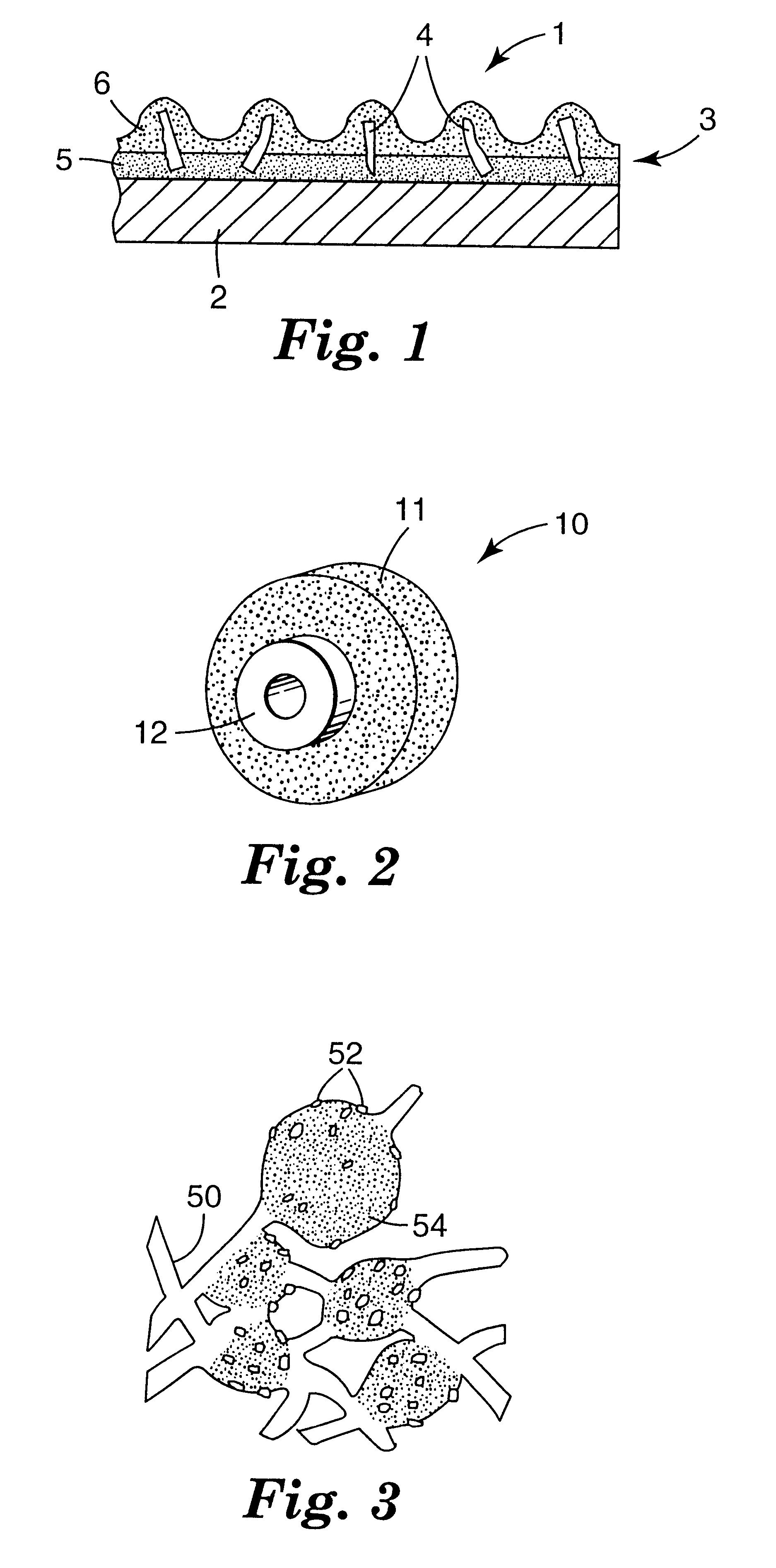
fused material was crushed by using a "Chipmunk" jaw crusher (Type VD; manufactured by BICO Inc., Burbank, Calif.) into (abrasive) particles and graded to retain the -25+30 and -30+35 mesh fractions (USA Standard Testing Sieves). These two mesh fractions were combined to provide a 50 / 50 blend. Thirty grams of the 50 / 50 blend of -25+30 and -30+35 mesh fractions were incorporated into a coated abrasive disc. The coated abrasive disc was made according to conventional procedures. The fused abrasive particles were bonded to 17.8 cm diameter, 0.8 mm thick vulcanized fiber backings (having a 2.2 cm diameter center hole) using a conventional calcium carbonate-filled phenolic make resin (48% resole phenolic resin, 52% calcium carbonate, diluted to 81% solids with water and glycol ether) and a conventional cryolite-filled phenolic size resin (32% resole phenolic resin, 2% iron oxide, 66% cryolite, diluted to 78% solids with water and glycol ether). The wet make resin weight was about 185 g / m...
example 2
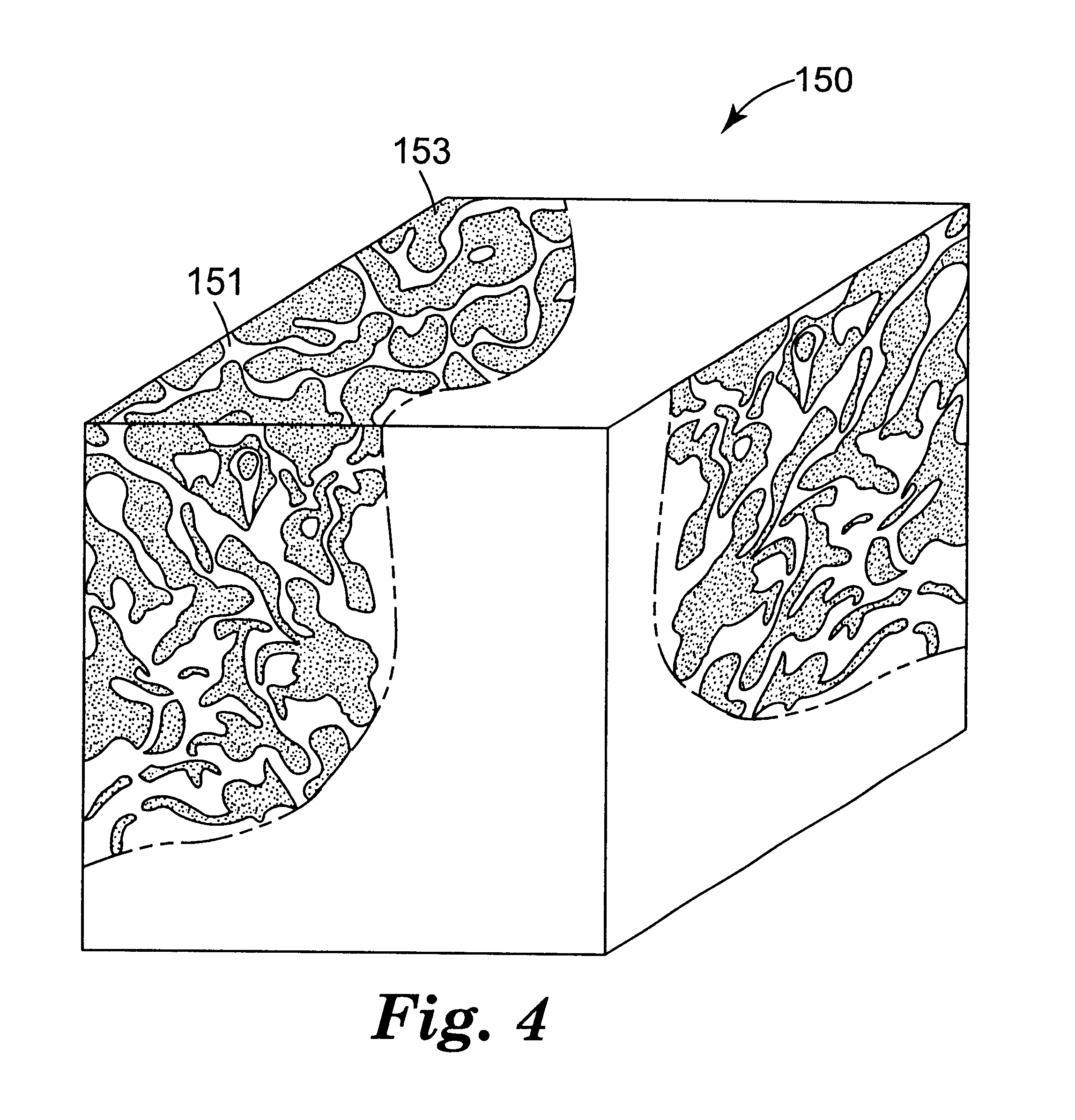
Several Example 2 abrasive particles (together with Example 3 and 4 abrasive particles) were also heated placed in a platinum crucible and heated to 1000.degree. C. at 50.degree. C. / hour, held at 1000.degree. C. for 8 hours (in air), and then cooled to room temperature at about 100.degree. C. / hour. The color of the Example 2 abrasive particles after heating was the same as before heating (i.e., white-red). The average microhardness of the Example 2 abrasive particles after heating was 14.3 GPa. The polished cross-sections prepared for the microhardness measurements were examined using the SEM in the secondary electron mode. The microstructure observed for the Example 2 abrasive particles after heating was substantially the same as the microstructure observed before heating.
The effect of two vitrified bonding materials on Example 2 abrasive particles were evaluated as follows. A first vitrified bond material was prepared by charging a plastic jar (43 / 8 inches (11.1 cm) in diameter; 4...
example 3
Several Example 3 abrasive particles (together with Example 2 and 4 abrasive particles) were also heated placed in a platinum crucible and heated to 1000.degree. C. at 50.degree. C. / hour, held at 1000.degree. C. for 8 hours (in air), and then cooled to room temperature at about 100.degree. C. / hour. The color of the Example 3 abrasive particles after heating was the same as before heating (i.e., white-blue). The average microhardness of the Example 3 abrasive particles after heating was 14.5 GPa. The polished cross-sections prepared for the microhardness measurements were examined using the SEM in the secondary electron mode. The microstructure observed for the Example 3 abrasive particles after heating was substantially the same as the microstructure observed before heating.
The effect of two vitrified bonding materials on Example 3 abrasive particles were evaluated as described in Example 2. The polished cross-sections were examined using the SEM in the secondary electron mode. The ...
PUM
| Property | Measurement | Unit |
|---|---|---|
| Fraction | aaaaa | aaaaa |
| Time | aaaaa | aaaaa |
| Percent by mass | aaaaa | aaaaa |
Abstract
Description
Claims
Application Information
 - R&D
- Intellectual Property
- Life Sciences
- Materials
- Tech Scout
- Unparalleled Data Quality
- Higher Quality Content
- 60% Fewer Hallucinations
Browse by: Latest US Patents, China's latest patents, Technical Efficacy Thesaurus, Application Domain, Technology Topic, Popular Technical Reports.
© 2025 PatSnap. All rights reserved.Legal|Privacy policy|Modern Slavery Act Transparency Statement|Sitemap|About US| Contact US: help@patsnap.com


