Auto-ignition of gasoline engine by varying exhaust gas retaining duration

a technology of auto-ignition and exhaust gas, which is applied in the direction of electric control, machines/engines, output power, etc., can solve the problems of difficult auto-ignition, inability to maintain auto-ignition, and advance in the closing timing of the intake valv

Inactive Publication Date: 2003-09-02
NISSAN MOTOR CO LTD
View PDF16 Cites 36 Cited by
  • Summary
  • Abstract
  • Description
  • Claims
  • Application Information

AI Technical Summary

Problems solved by technology

Further, closing timing of the intake valve advances during operation with load where auto-ignition is difficult to accomplish.
The known technique is satisfactory to some extent, however, involves a potential problem that auto-ignition might not be sustained against variation of temperature conditions in the cylinder.
However, if closing timing of exhaust valve is always advanced in the above manner to retain sufficient amount of exhaust gas to deal with the undesired drop in cylinder wall temperature, the temperature in the cylinder is always elevated, inducing cooling loss thereby deteriorating fuel economy.

Method used


Image

  • Auto-ignition of gasoline engine by varying exhaust gas retaining duration
  • Auto-ignition of gasoline engine by varying exhaust gas retaining duration
  • Auto-ignition of gasoline engine by varying exhaust gas retaining duration

Examples


Embodiment Construction

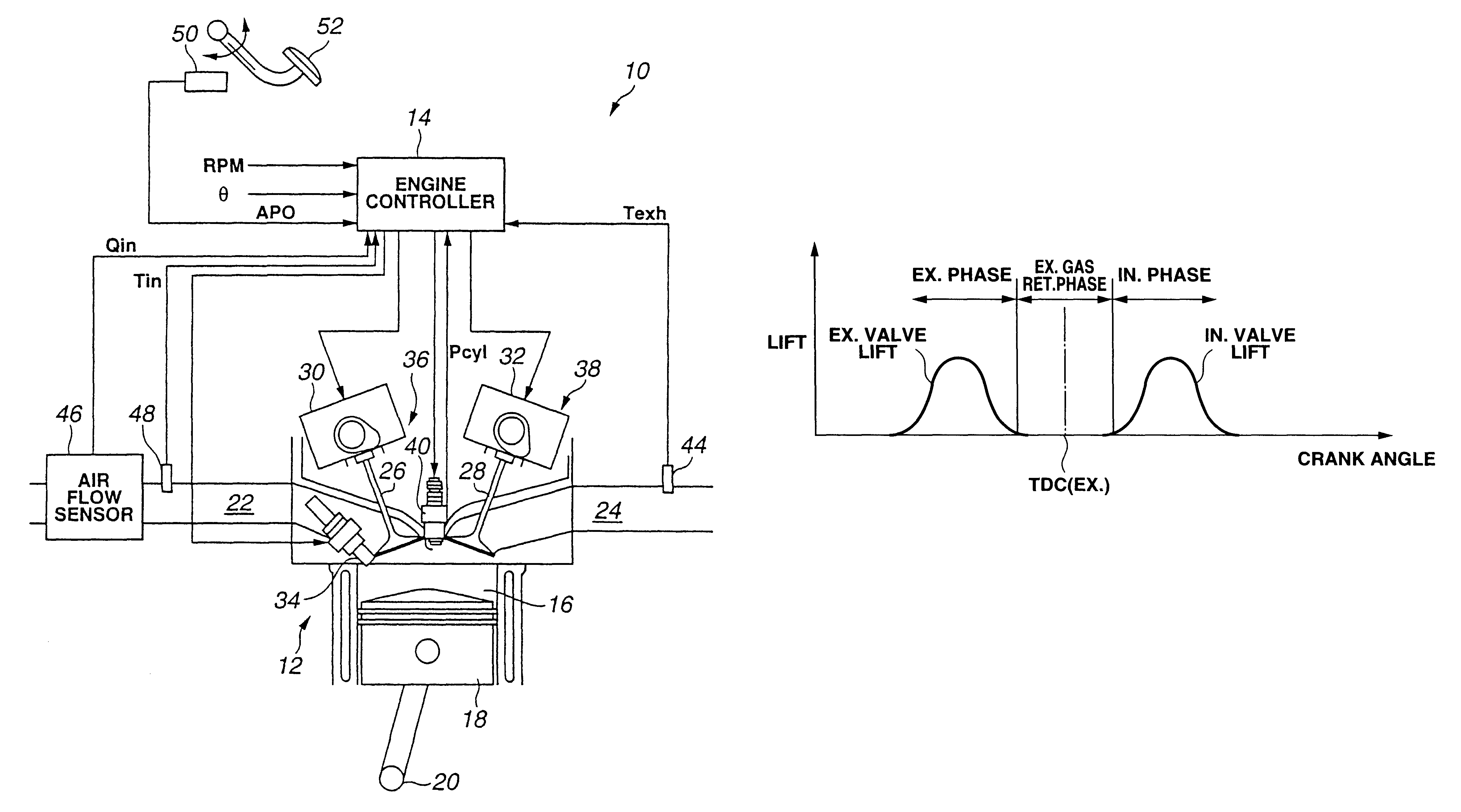
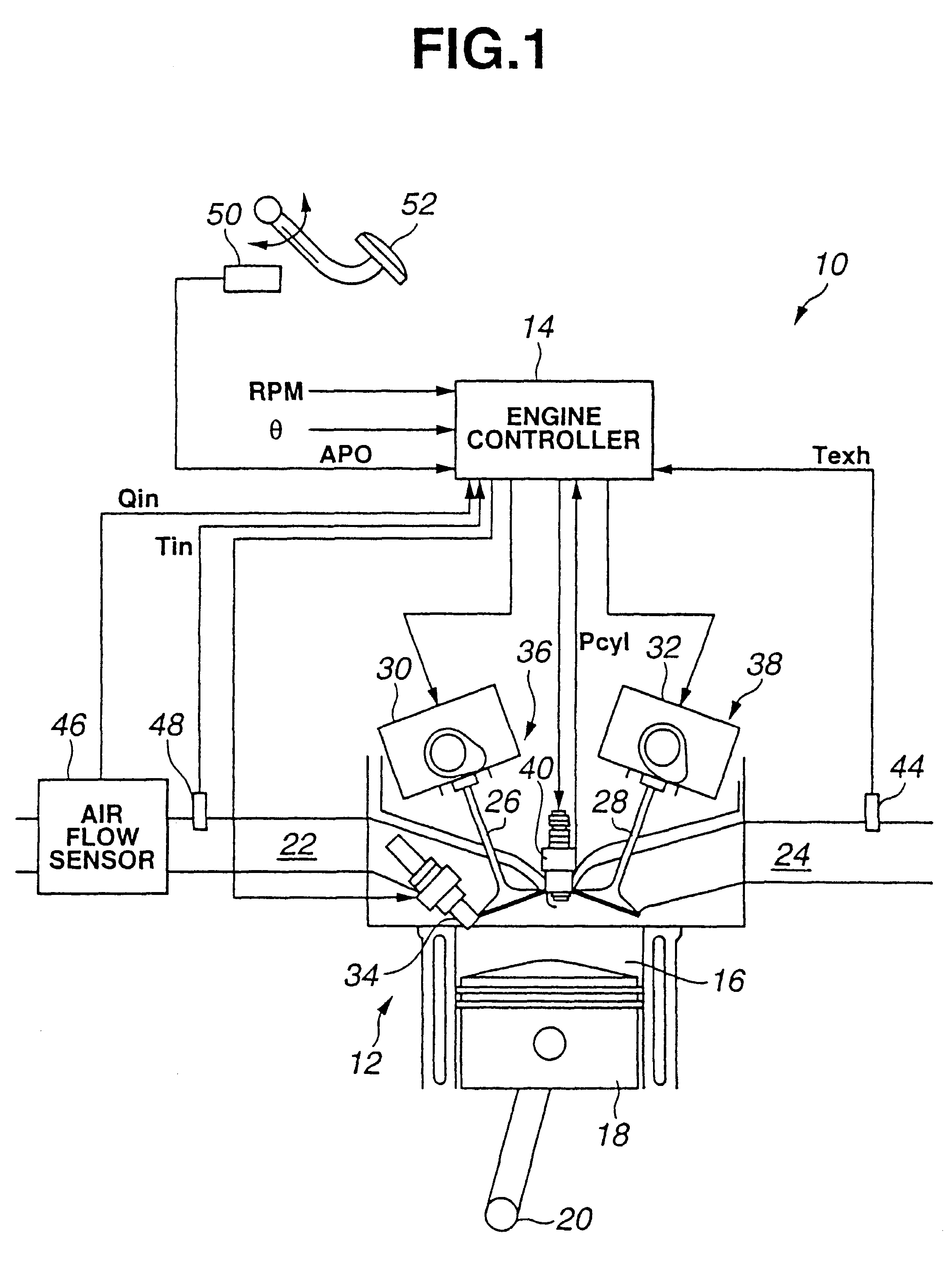
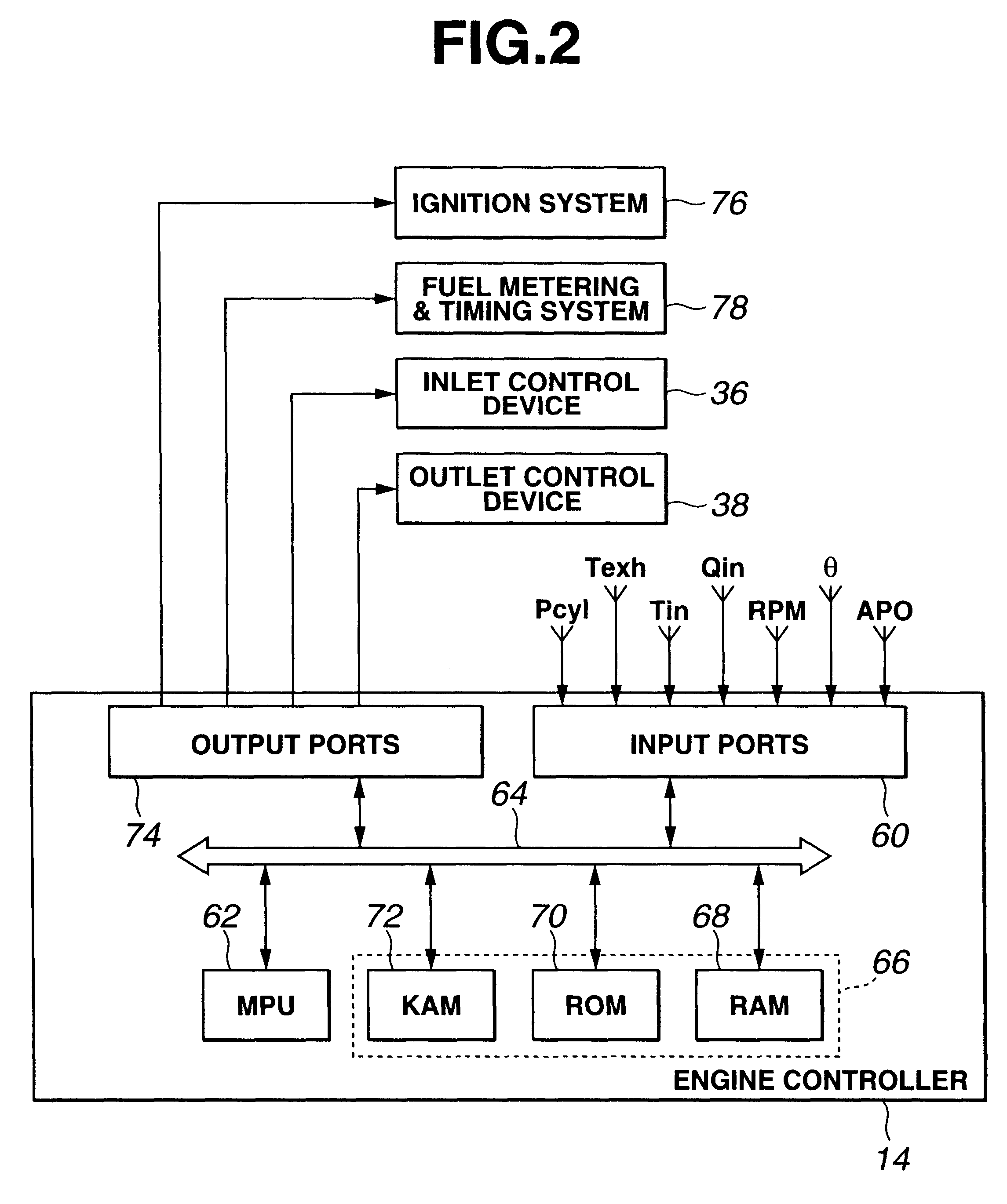
FIG. 1 provides a block diagram of a system or method for controlling auto-ignition of gasoline fuel of a four-stroke internal combustion engine. System 10 includes an internal combustion engine, indicated generally by reference numeral 12, in communication with an engine controller 14.

In FIG. 1, the area of a combustion chamber of engine 12 is shown. Engine 12 has at least one cylinder 16 in which a piston 18 is located and connected to crankshaft 20 Combustion chamber or cylinder 16 is shown communicating within intake manifold 22 and exhaust manifold 24 via intake and exhaust valves 26 and 28, which are actuated by variable valve controllers 30 and 32. Fuel injector 34 of a fuel injection device is shown directly communicating with the combustion chamber within cylinder 16 for spraying gasoline fuel directly therein.

Inlet flow into cylinder 16 is governed by an inlet control device 36. Outlet flow from cylinder 16 is governed by an outlet control device 38. In a preferred embodim...


PUM


Abstract

A system and method controls auto-ignition of gasoline fuel within a cylinder of an internal combustion engine by varying an exhaust gas retaining duration. A generator provides a parameter indicative of combustion event within the cylinder. An engine controller adjusts an inlet control device and an outlet control device to retain exhaust gas for subjecting the retained exhaust gas to compression. In order to vary duration of the exhaust gas retaining phase, closing timing of the outlet control device is varied based on the parameter.

Description

1. Field of the InventionThe present invention relates to a system and method for controlling auto-ignition of a four-stroke gasoline internal combustion (IC) engine, and an auto-ignition type IC engine.2. Description of Related ArtJP-A 10-266878 discloses a technique to accomplish auto-ignition of gasoline fuel over a predetermined load range from low load to middle load by adjusting closing timing of an exhaust valve as well as opening and closing timings of an intake valve. According to this known technique, over the predetermined load range, an opening timing of the exhaust valve is held invariable at a crank position before a bottom dead center (BDC) position of expansion stroke against variations of load request, but a closing timing of the exhaust valve is adjusted to varying crank positions before a top dead center (TDC) position of exhaust stroke against varying load request. A throttle valve is fully opened over this predetermined load range. The closing timing of the exha...

Claims


Application Information

Patent Timeline
Patent Type & Authority Patents(United States)
IPC IPC(8): F02D35/02F02D13/02F02D43/00F02D41/30F02D41/38F02B1/12F02B1/00F02B75/00F02M25/07F02B75/12F01L13/00F01L1/34F02D41/02F02D41/14
CPCF02B1/12F02D13/0207F02D13/0265F02D35/023F02D41/0062F02D41/3035F02D41/3818F02D43/00F02B2075/125F02D41/1497F02D2041/001F02M25/0752Y02T10/18Y02T10/123Y02T10/47F02M26/01Y02T10/12Y02T10/40
Inventor HIRAYA, KOJIMIYAKUBO, HIROSHITERAJI, ATUSHI
Owner NISSAN MOTOR CO LTD
Why Eureka
Try Eureka