Oil mist discharger

a self-adjusting, oil mist technology, applied in the direction of mechanical equipment, metal-working machine components, manufacturing tools, etc., can solve the problems of unacceptably costly adjustment devices or complication of the whole system, and the treatment is expensive, and the manual adjustment of the oil mist discharge performance is required

Inactive Publication Date: 2003-09-23
TANAKA IMPORT GROUP +1
View PDF5 Cites 7 Cited by
  • Summary
  • Abstract
  • Description
  • Claims
  • Application Information

AI Technical Summary

Benefits of technology

It is another object of the present invention to provide an oil mist discharger which is far more reliable than conventional oil mist dischargers.
It is still another object of the present invention to provide an oil mist discharger at a lower manufacturing cost than conventional oil mist dischargers by simplifying the overall structure.
An oil mist discharger of the present invention is utilized with a cutting or drilling tool to machine objects such as metallic or plastic materials. The oil mist discharger provides a mist stream of lubricant or cutting oil onto the cutting / drilling spot of the object being machined most effectively and optimally. Insufficient or excessive provision of cutting oil in inappropriate oil particle sizes is avoided as the oil mist discharger of the present invention is provided with a self-adjusting mechanism to automatically discharge an optimal amount of cutting oil in an optimal mist form.
The oil mist discharger of the present invention utilizes a novel flow regulator of a compact size, which effectively and efficiently utilizes the differential pressure between air pressure and oil pressure so as to optimally draw cutting oil from an oil tank into air and optimally blend the introduced cutting oil with the air for discharging from the discharge nozzle against a cutting or drilling tool or against a machining spot. Such functions are provided in an automatic manner.
When the caliber of the nozzle is "large," more cutting oil is blended in the air stream. The air stream carrying "much" oil comes out of all or a plurality of the sub-passage units into the agitation chamber in "fine" jet streams, facilitating excellent blending of the cutting oil and air in the agitation chamber into a micro particle oil mist. On the other hand, when the caliber of the nozzle is "small," a well blended micro particle oil mist is provided in the agitation chamber.

Problems solved by technology

Used cutting oil is conventionally treated in a costly way for recycling or disposal or simply disposed of in the nature.
Conventionally, very time-consuming and highly burdensome manual adjustment of oil mist discharge performance is required every time cutting / drilling tools or discharge nozzles are changed for particular objects to be machined or for desired machining dimensions.
Simplification of such adjustments in a conventional way may be possible, however not without unacceptably costly adjustment devices or complication of the whole systems.
If the adjustment of the conventional oil mist discharger is inappropriate, excessive or insufficient oil or lubricant in an inadequately formed mist will be discharged.

Method used


Image

  • Oil mist discharger
  • Oil mist discharger
  • Oil mist discharger

Examples


Embodiment Construction

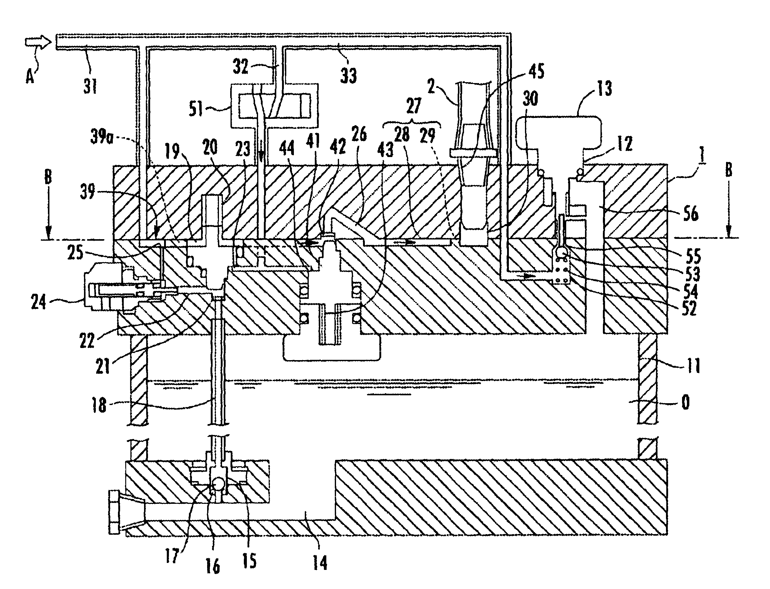
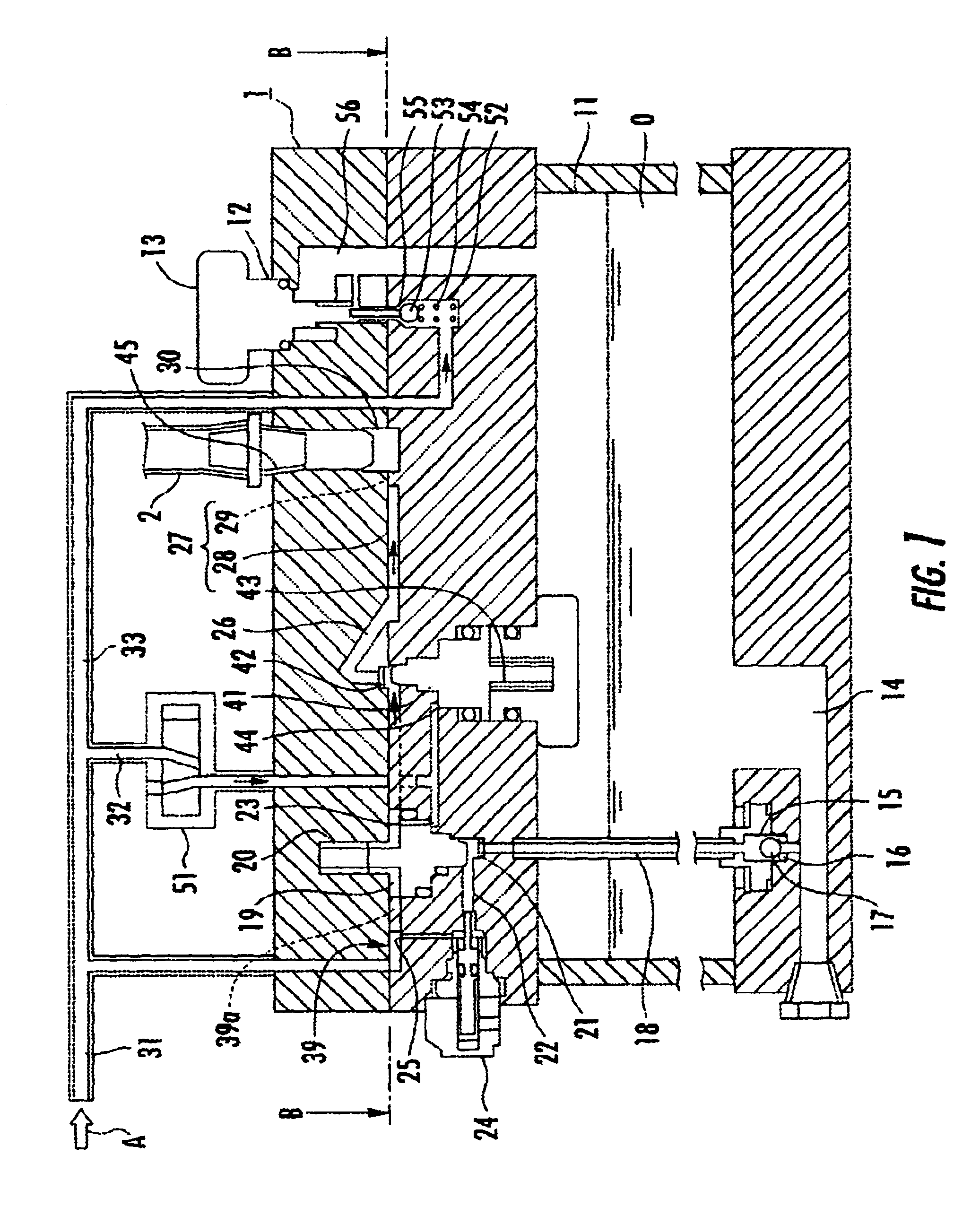
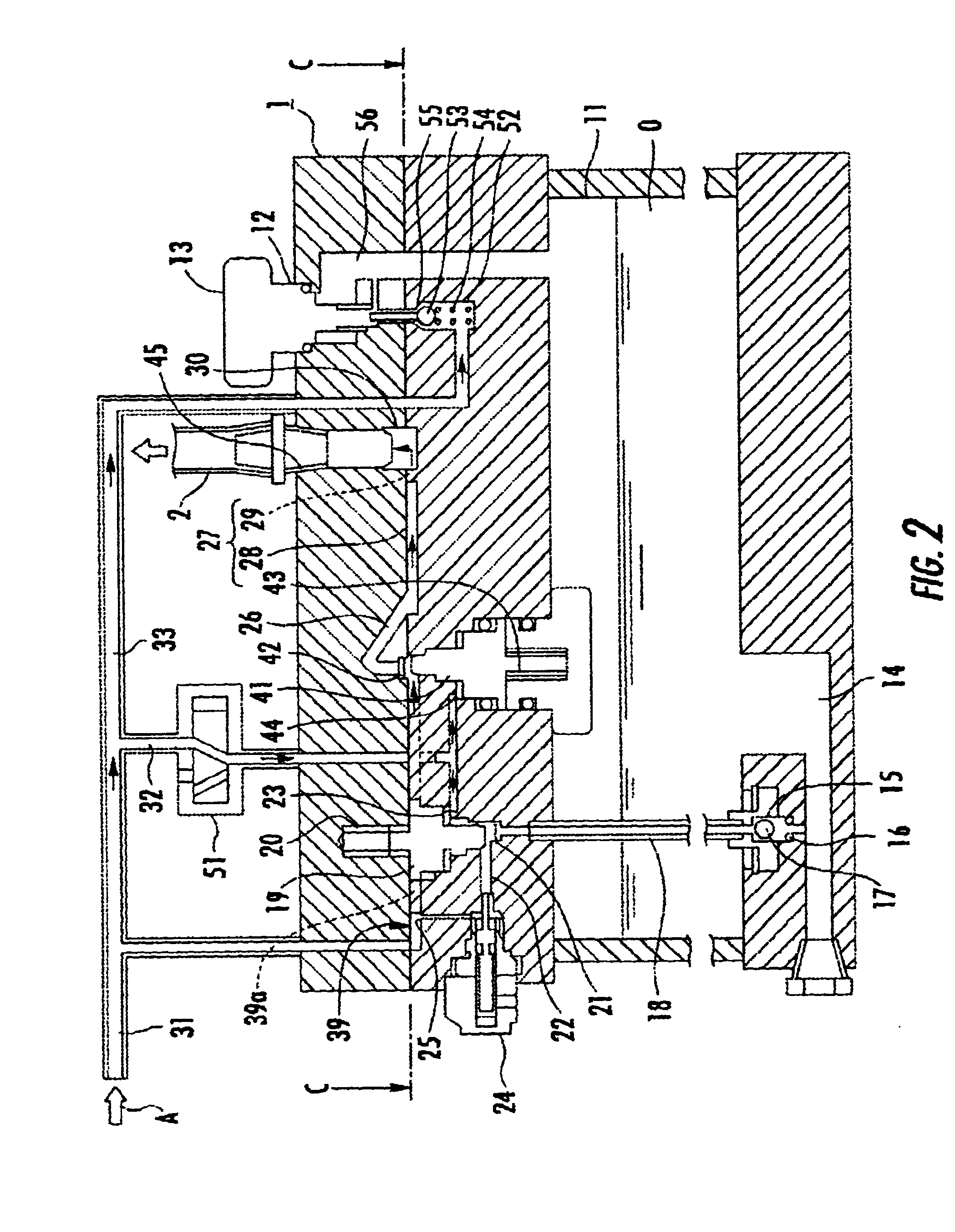
Before the present invention is further described using the accompanying drawings, it is important to be noted that the accompanying drawings are intended to be utilized for the description of the inventive concept only, and they do not faithfully depict the relative sizes, dimensions, locations or orientations of the devices and members shown. For example, the "flow regulator 27" and the "oil feed chamber 39" are actually provided much closer to each other or rather as "a unit." All devices and members shown between the flow regulator 27 and the oil feed chamber 39 are to be provided in actuality not to hinder the "positionally close" relationship between the flow regulator 27 and the oil feed chamber 39.

An oil mist discharger 1 according to an embodiment of the present invention is shown in FIG. 1 in its non-operating state and in FIG. 2 in its operating state. The oil mist discharger 1 discharges a mist of cutting oil "O" stored in a built-in oil tank 11 at an optimal discharge r...


PUM


Abstract

An oil mist discharger (1) is disclosed. The oil mist discharger (1) utilizes a flow regulator (27) which comprises a main passage (28), sub-passages (29) and an agitation chamber (30). Differential pressure between air and oil is created and utilized in drawing oil into an oil feed chamber (39) to be mixed with air. The oil-containing air is sent to the flow regulator (27) and fed into the agitation chamber (30) via the main passage (28) and sub-passages (29) in jet streams to be transformed into a well blended oil mist, which is discharged from a discharge nozzle.

Description

This application claims the priority date of Apr. 18, 2000 for Japanese Patent Application No. 2000-116261.1. Field of the InventionThis invention generally relates to a mist discharger. More particularly, this invention relates to a self-adjusting oil mist discharger.2. Background ArtConventionally, cutting oil such as lubricant is sprayed or dropped onto a cutting / drilling portion of a metallic or synthesized resin material being machined for lubrication and / or cooling so as to provide smooth cutting, prevent heat generation and eliminate damage to the cutting / drilling tool and the object material under treatment.Of late, attempts have been made to reduce the amount of cutting oil used in cutting / drilling operations in order to reduce machining costs by saving on cutting oil and more importantly in consideration of the environmental preservation. Used cutting oil is conventionally treated in a costly way for recycling or disposal or simply disposed of in the nature.A most desirous...

Claims


Application Information

Patent Timeline
Patent Type & Authority Patents(United States)
IPC IPC(8): B23Q11/10B05B13/00F16N7/00F16N7/34B05B7/00B05B7/26B05B7/24B05B7/32
CPCB05B13/00B23Q11/10F16N7/34B05B7/0012B05B7/267B23Q11/1046Y02P70/10
Inventor UENO, KOJITANAKA, MOTOHIRO
Owner TANAKA IMPORT GROUP
Why Eureka
Try Eureka