Light source optical system and projector having first and second lamps of different spectral distributions

a technology of optical system and projector, which is applied in the field of liquid crystal projector, can solve the problems of low purity of red color of image displayed, low overall brightness of image displayed, and deterioration of reproduction

Inactive Publication Date: 2003-09-23
SEMICON ENERGY LAB CO LTD
View PDF17 Cites 34 Cited by
  • Summary
  • Abstract
  • Description
  • Claims
  • Application Information

AI Technical Summary

Benefits of technology

The present invention uses two or more lamps having differing light spectral distributions for a light source of a projector, in particular a liquid crystal projector. With the above structure, light with a wavelength range of low brightness emitted from one lamp is compensated by light emitted from the other lamp, and the light irradiated from the light source has good balance in brightness between red, blue, and green colors. The balance in brightness of red color, blue color, and green color light becomes good by the above structure, and it becomes possible to form an image having good color purity and high brightness overall on a screen.
For example, a lamp in which the red color brightness is lower than the brightnesses of blue and green colors, and a lamp in which the red color brightness is higher than that of blue and green colors are used as a single light source (light sources having the structure of the present invention are hereafter referred to as light source optical systems) in a liquid crystal projector. The red, blue, and green color brightness balance and the color reproduction, of an image displayed on a screen by the liquid crystal projector is improved, and the overall brightness of the image can be increased by the above structure.

Problems solved by technology

However, although the balance in brightness between the red, green, and blue colors of light becomes good, the overall brightness of the image displayed becomes low.
In this case, however, even though the brightness becomes higher, the purity of the red color of the image displayed is low, and when a red color image is to be displayed, it gets displayed as orange in color and the reproduction deteriorates.

Method used


Image

  • Light source optical system and projector having first and second lamps of different spectral distributions
  • Light source optical system and projector having first and second lamps of different spectral distributions
  • Light source optical system and projector having first and second lamps of different spectral distributions

Examples


embodiment 1

A three panels type liquid crystal projector using the light source optical system of the present invention shown in the embodiment mode is explained in Embodiment 1.

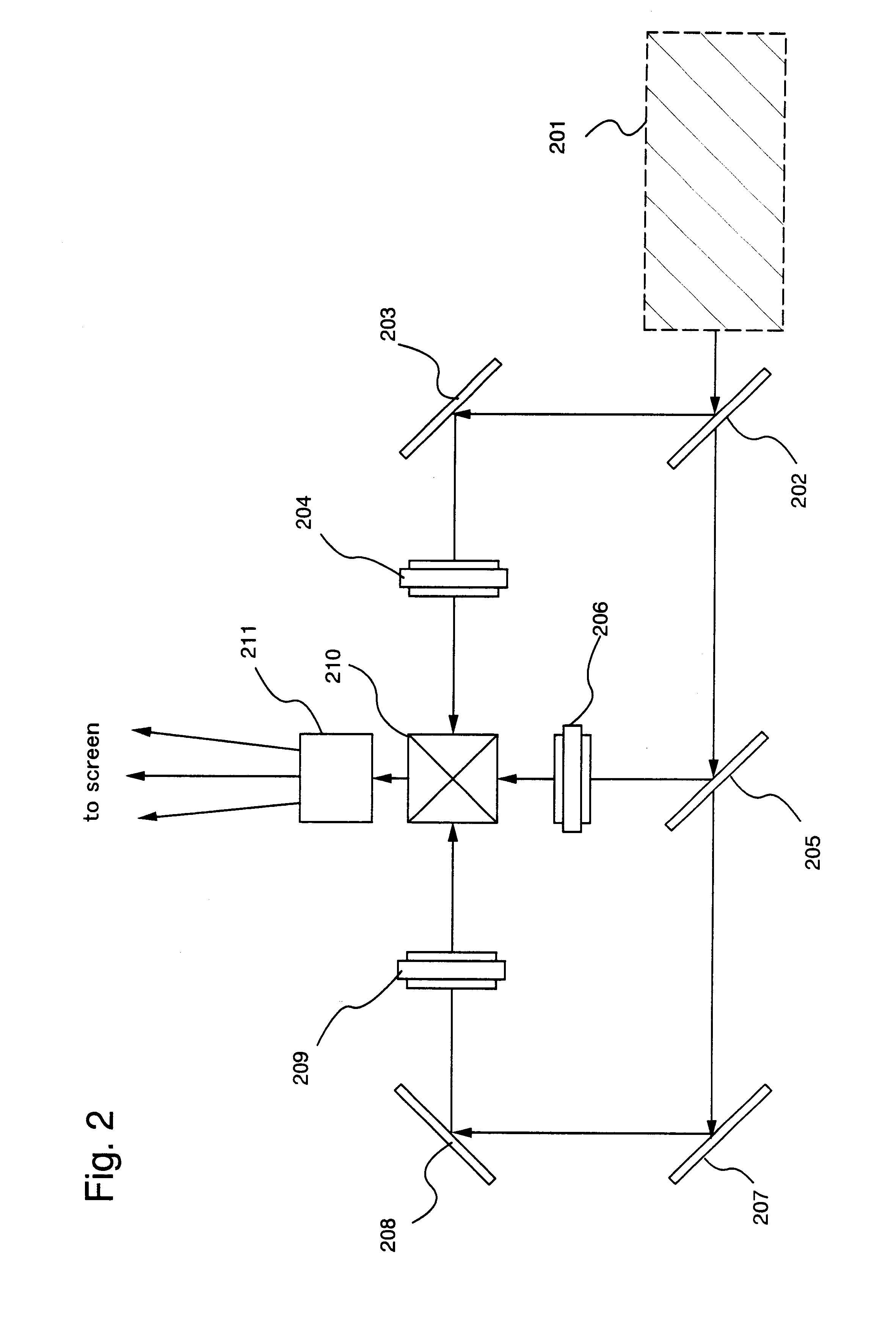
A three panels liquid crystal projector of the present invention is shown in FIG. 2. A high pressure mercury lamp and a halogen lamp are used in a light source optical system 201 in Embodiment 1. Note that the present invention is not limited to the use of these two lamps. Irradiation light formed by combining light from the high pressure mercury lamp and light from the halogen lamp is irradiated from the light source optical system 201.

Light emitted from the high pressure mercury lamp and having a low brightness wavelength range is compensated by light emitted from the halogen lamp, and therefore the red, blue, and green color brightnesses of light emitted from the light source optical system 201, and it color purity balance, are good. The color reproduction of an image formed on a screen therefore becomes good, and th...

embodiment 2

As An example of a light source optical system of the present invention differing from the example shown by the embodiment mode is shown in Embodiment 2.

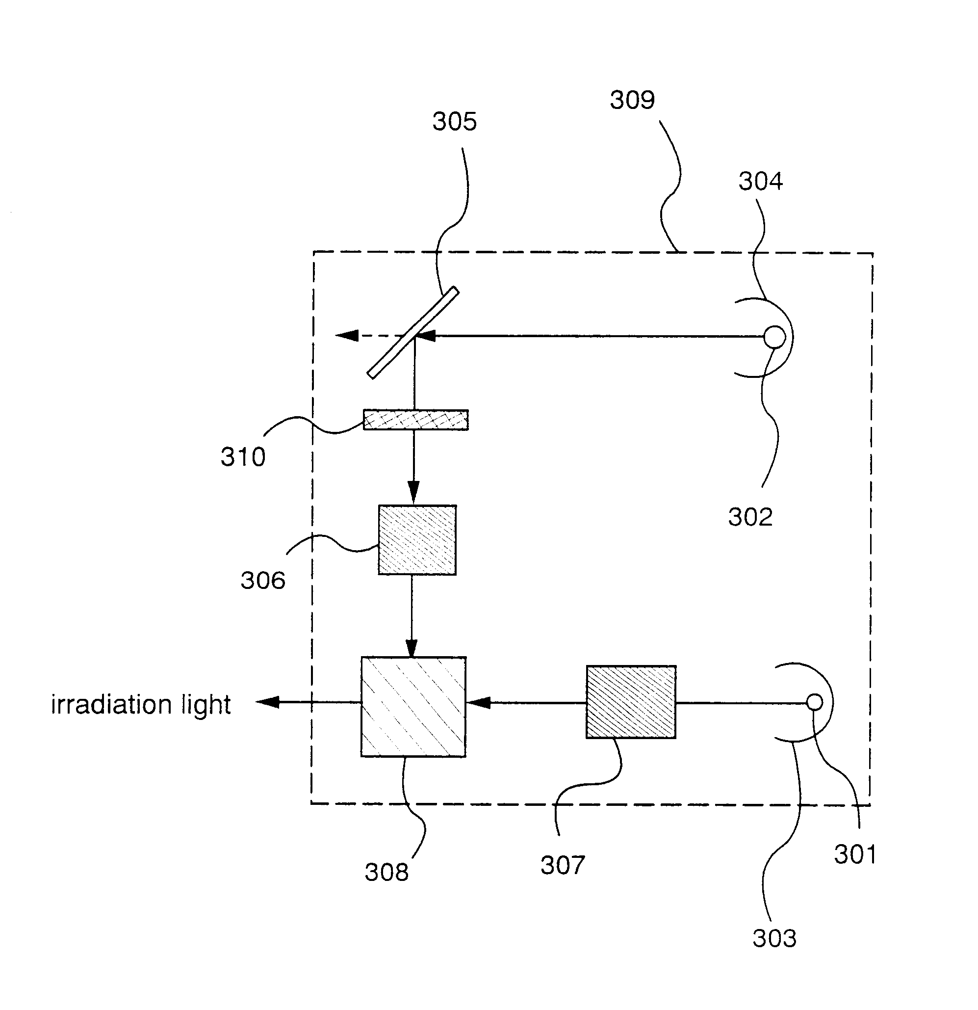
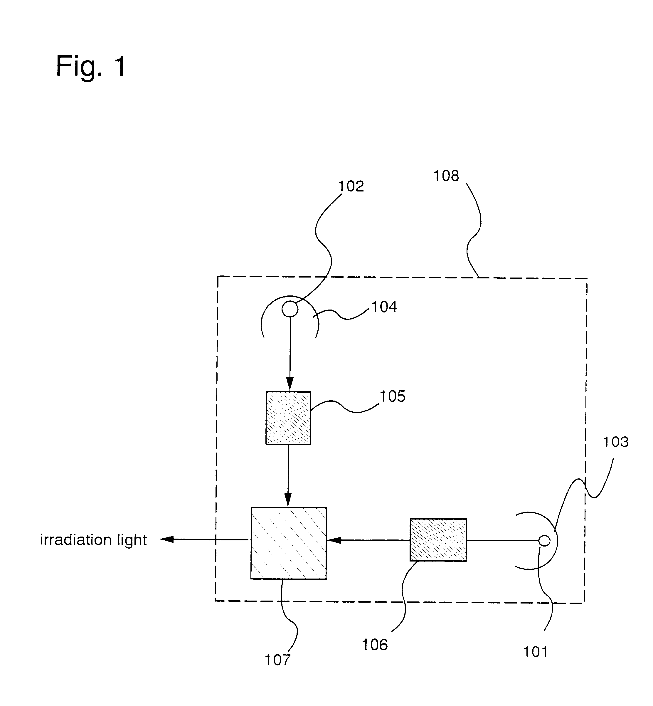
FIG. 3 shows a light source optical system of the present invention. A high pressure mercury lamp 301 and a halogen lamp 302 are formed within a light source optical system 309.

Light from the high pressure mercury lamp 301 is condensed by a high pressure mercury lamp reflector 303, and enters to a high pressure mercury lamp condensing system 307.

Further, light from the halogen lamp 302 is condensed by a halogen lamp reflector 304 and enters to a light source optical system R dichroic mirror 305. The light is separated by reflecting only the light having a red color wavelength range from the light emitted from the halogen lamp and enters to the light source optical system R dichroic mirror 305, and this enters to an optical system filter 310.

The red color light from the halogen lamp 302 is adjusted in brightness by the optical system...

embodiment 3

An example which differs from the three panels type projector used in the light source optical system of the present invention shown in Embodiment 1 is explained in Embodiment 3.

Please refer to FIG. 4. FIG. 4 is a schematic diagram of a three panels type projector of Embodiment 3. Reference numeral 401 denotes a light source optical system of the present invention. The light source optical system of Embodiment 3 has the form shown by the embodiment mode and by Embodiment 2 of the present invention. White color irradiation light possessing a spectrum of red color, green color, and blue color wavelength ranges is irradiated from the light source optical system 401.

The white color irradiation light irradiated from the light source optical system 401 enters to an R dichroic mirror 402. Only the red color wavelength range of light from the irradiation light incident to the R dichroic mirror 402 is reflected. The red color light reflected in the R dichroic mirror 402 is then reflected by ...


PUM

PropertyMeasurementUnit
thicknessaaaaaaaaaa
thicknessaaaaaaaaaa
pressureaaaaaaaaaa

Abstract

A light source optical system capable of forming an image having good balance in brightness of red, blue, and green color light, having high overall brightness, and having good color reproducibility, on a screen is provided. The light source optical system has a first lamp, a second lamp, and a condensing optical system for synthesizing a first light emitted from the first lamp and a second light emitted from the second lamp to form irradiation light. The light source optical system is characterized in that the first light and the second light have mutually differing spectral distributions.

Description

1. Field of the InventionThe present invention relates to a light source used in a projector which projects an image on a screen. Further, the present invention relates to a projector using the projector light source, and in particular, to a liquid crystal projector using the a liquid crystal panel.2. Description of the Related ArtTechniques for manufacturing a semiconductor device in which a semiconductor thin film is formed on a low cost glass substrate, for example a thin film transistor (TFT), have been developing rapidly. The reason is the fact that the demand for an active matrix type liquid crystal panel becomes high.A thin film transistor (pixel TFT) is arranged in each of several hundred thousands to several millions of pixels arranged in a matrix state in an active matrix type liquid crystal panel (liquid crystal panel). Electric charges inputted to a pixel electrode on each pixel is controlled by the pixel TFTs.Furthermore, projecting type display panels using the liquid ...

Claims


Application Information

Patent Timeline
Patent Type & Authority Patents(United States)
IPC IPC(8): G02F1/13G02F1/1335G03B21/26H04N9/31H04N5/74G02B27/00G02B27/14G02F1/13357
CPCG02B27/145G02B27/148G02B27/149G03B33/12H04N9/3164H04N9/3197G03B21/2013G03B21/208G02F1/133609G02F2001/133622H04N5/7441G02F1/133622
Inventor YAMAZAKI, SHUNPEIHIROKI, MASAAKIFUKADA, TAKESHI
Owner SEMICON ENERGY LAB CO LTD
Why Eureka
Try Eureka