Hard metal drill bit for use on a drill

a cutting tip and drill bit technology, which is applied in the direction of turning tools, boring/drilling tools, reaming tools, etc., can solve the problems of hard metal cutting tip being subjected to extreme wear in the outer cutting region, reducing the service life of the drill bit, and welded work material particles to the cutting fa

Inactive Publication Date: 2003-10-07
EISCHEID KARL
View PDF8 Cites 23 Cited by
  • Summary
  • Abstract
  • Description
  • Claims
  • Application Information

AI Technical Summary

Problems solved by technology

A disadvantage in such cases is that the hard-metal cutting tip is subjected to extreme wear in the outer cutting regions due to the high peripheral speeds.
This decreases the service life of the drill.
The essential causes of this wear are, on the one hand, the rubbing action of the cutting tip on the working surface, which can cause particles of work material to become welded to the cutting face.
Another cause of wear is diffusion, which, due to the high temperatures produced by the friction, causes metal atoms to migrate from the cutting material into the overflowing chip, thereby weakening the cutting material, which can lead to breakage.
This makes for a longer service life, which is the period of use of the tool
A disadvantage in such cases is that the hard-metal cutting tip is subjected to extreme wear in the outer cutting regions due to the high peripheral speeds.
This decreases the service life of the drill.
The essential causes of this wear are, on the one hand, the rubbing action of the cutting tip on the working surface, which can cause particles of work material to become welded to the cutting face.
Another cause of wear is diffusion, which, due to the high temperatures produced by the friction, causes metal atoms to migrate from the cutting material into the outflowing chip, thereby weakening the cutting material, which can lead to breakage.
This makes for a longer service life, which is the period of use of the tool to attainment of a permissible degree of wear.
The outer regions of the primary cutting edges, in particular, are severely stressed by the high rotation speeds and the attendant high peripheral speeds.

Method used


Image

  • Hard metal drill bit for use on a drill
  • Hard metal drill bit for use on a drill

Examples


Embodiment Construction

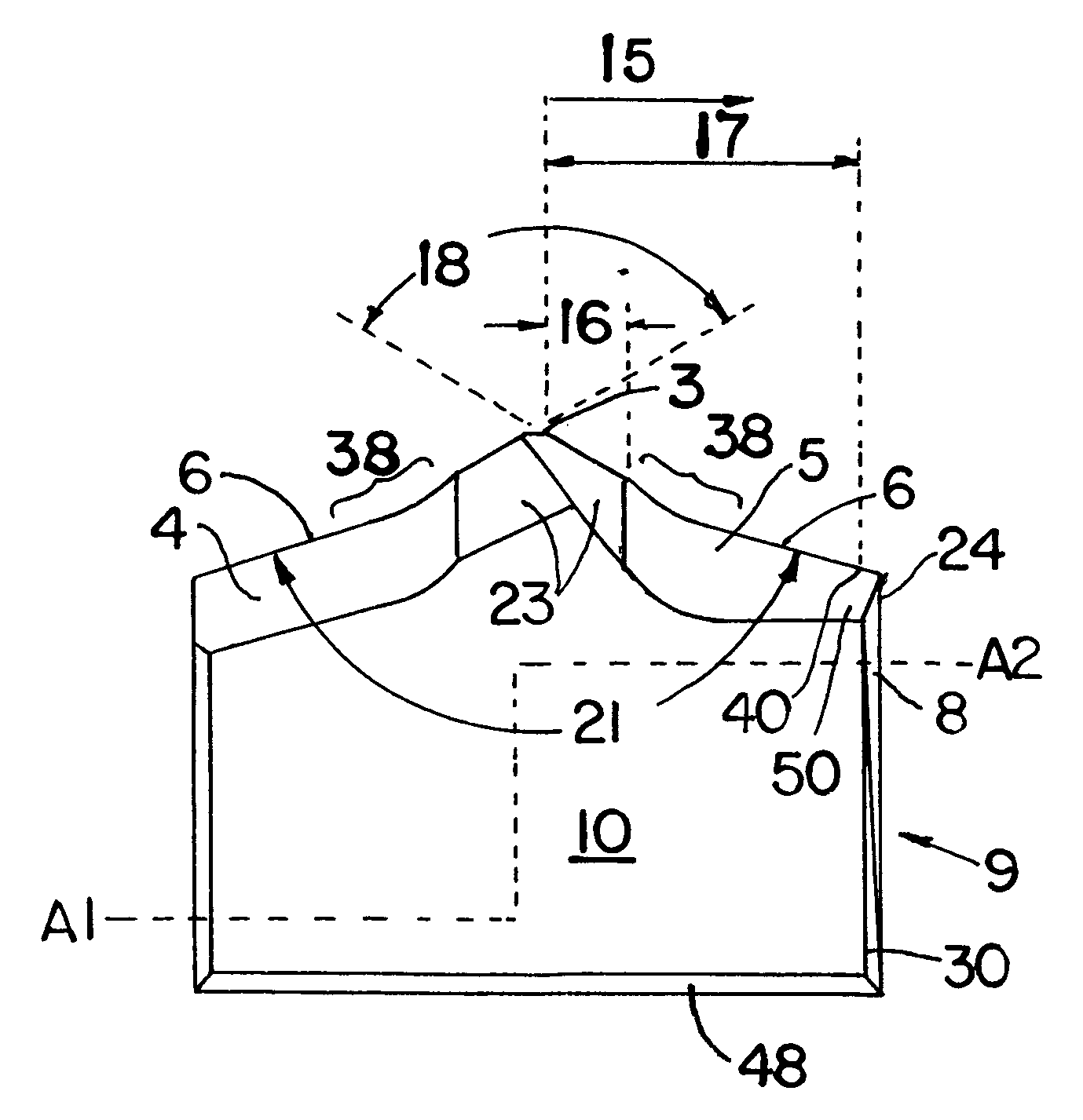
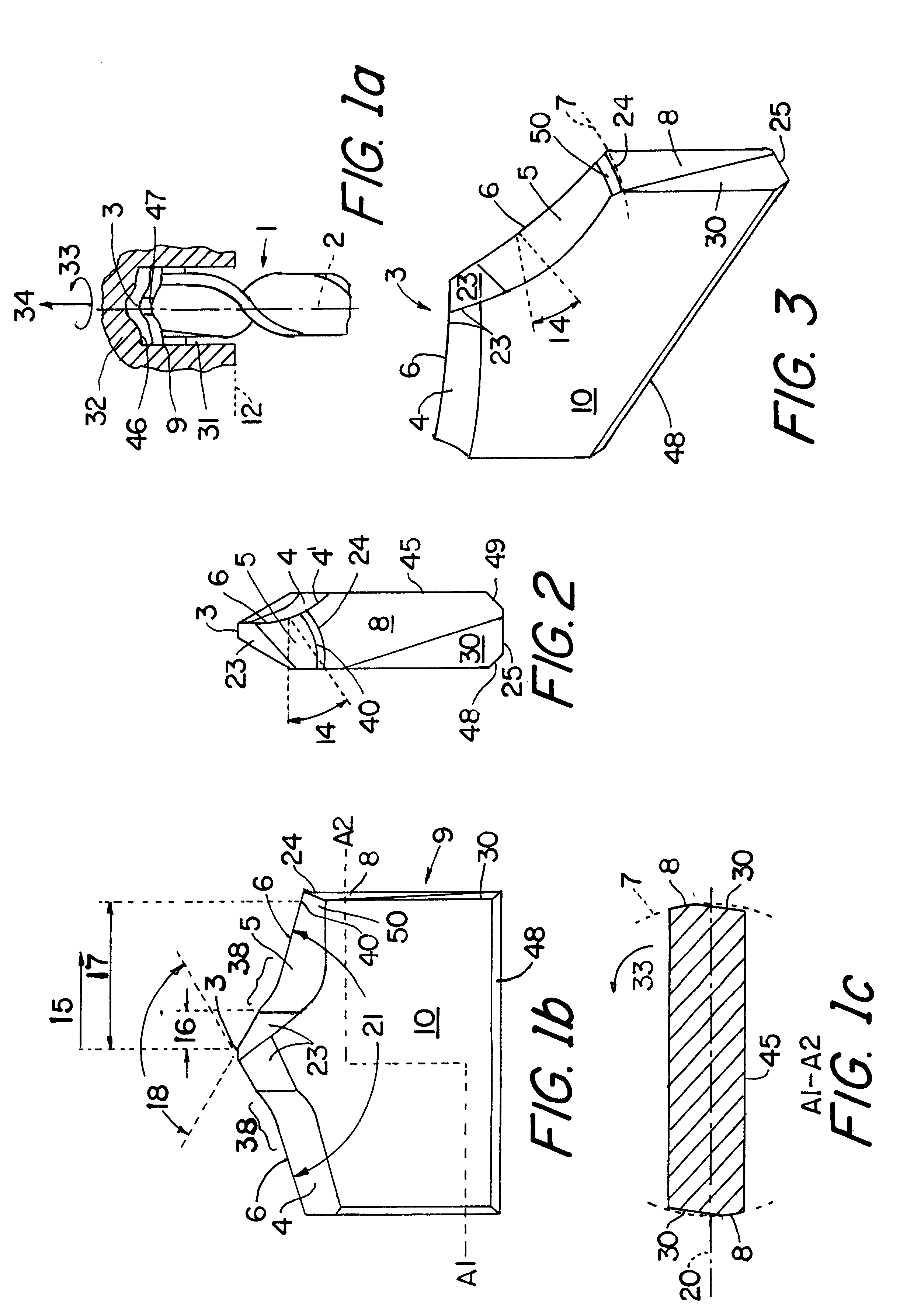
FIG. 1a schematically depicts the basic structure of a drill 1 with a hard-metal cutting tip placed thereon. The drill 1 is preferably a hammer drill or a percussion drill. The drill 1 is shown in a workpiece drillhole 31 inside a workpiece 32 to be machined. The drill 1 has a spiral shape that facilitates the carrying off of material machined from the workpiece drillhole 31. The hard-metal cutting tip comprises a drill point 3 through which the axis 2 of rotation of the drill 1 passes. The hard-metal cutting tip projects at the drill point 3 beyond the end 47 of the drill 1 and at its small sides 9 beyond the outer diameter of the drill 1. The feed motion 34 of the drill 1 proceeds longitudinally to the axis 2 of rotation of the drill 1. The cutting motion 33 of the drill 1 proceeds perpendicularly to the feed motion 34. The cutting motion 33 and the feed motion 34 are therefore borne substantially by the hard-metal cutting tip. The surface 46 of the workpiece 32 being machined tha...


PUM

PropertyMeasurementUnit
clearance angleaaaaaaaaaa
point angleaaaaaaaaaa

Abstract

The invention concerns a hard-metal cutting tip for use on a drill, particularly on a rock or concrete drill, including a drill point (3) extending through an axis of rotation of the drill, primary cutting edges (6) that slope downwardly on both sides, each composed of a primary land (4) and a primary flank (5), the primary flank (5) forming at the primary cutting edge (6) a primary lip clearance angle (14) with a plane perpendicular to the axis of rotation. To provide a hard-metal cutting tip that possesses high cutting, feed, bending and breaking strength and wear resistance, especially at its outer regions subjected to high peripheral speeds, the hard-metal cutting tip is realized such that the primary lip clearance angle (14) formed at the primary cutting edge (6) decreases with increasing distance from the drill point (3).

Description

(1) Field of the InventionThe invention relates to a hard-metal cutting tip for use on a drill, particularly on a rock or concrete drill, the cutting tip comprising a drill point for extending through an axis of rotation of the drill, and primary cutting edges that slope downwardly on both sides, each composed of a primary land and a primary flank, the primary flank forming at the primary cutting edge a primary tip clearance angle with a plane of the workpiece perpendicular to the axis of rotation of the drill.(2) Description of the Prior ArtKnown are hard-metal cutting tips for percussion or hammer drills, comprising primary lands and flanks that slope evenly downwardly and primary cutting edges. The drill point is formed by a chisel edge that connects the primary cutting edges. A disadvantage in such cases is that the hard-metal cutting tip is subjected to extreme wear in the outer cutting regions due to the high peripheral speeds. This decreases the service life of the drill. The...

Claims


Application Information

Patent Timeline
Patent Type & Authority Patents(United States)
IPC IPC(8): B23B51/02B23B51/00
CPCB23B51/00B23B51/0009B23B51/02B23B2226/75Y10T408/9093B23B2251/14B23B2251/50Y10T408/9097B23B2251/04B23B51/00035
Inventor EISCHEID, KARL
Owner EISCHEID KARL
Why Eureka
Try Eureka