Method for creation of planar or complex wavefronts in close proximity to a transmitter array

a transmitter array and complex wavefront technology, applied in the field of pseudoplane wave generators, can solve the problems of difficult, or impossible, within the confines of an anechoic chamber, test the response, and none of these devices, however, disclose the generating of an electromagnetic environmen

Inactive Publication Date: 2003-10-28
DONALD E VOSS D B A VOSS SCI
View PDF10 Cites 17 Cited by
  • Summary
  • Abstract
  • Description
  • Claims
  • Application Information

AI Technical Summary

Problems solved by technology

However, it is difficult, or impossible, within the confines of an anechoic chamber, to test the response and behavior of electronic equipment housed within an electrically large object, and coupled to the plane wave environment via multiple distributed, apertures and / or wire penetrations.
None of these devices, however, disclose generating an electromagnetic environment with multiple plane wave-like regions located in multiple, possibly disconnected, user specified positions, and with the capability to produce two, and three dimensional field distributions.
In addition, these devices do not teach the use of an arbitrary number of electromagnetic transmitting stations that can be distributed about an object under test, almost arbitrarily.
Also, these devices are not configured to produce a near field plane-wave-like electromagnetic environment by the utilization of a Genetic Algorithm.
The generation of plane wave electromagnetic environments at RF and electrical frequencies (typically in the 20 MHZ-20 GHz frequency range) for testing the response and behavior of electronic equipment can be difficult, or impossible, within the confines of an anechoic chamber.

Method used


Image

  • Method for creation of planar or complex wavefronts in close proximity to a transmitter array
  • Method for creation of planar or complex wavefronts in close proximity to a transmitter array
  • Method for creation of planar or complex wavefronts in close proximity to a transmitter array

Examples


Embodiment Construction

)

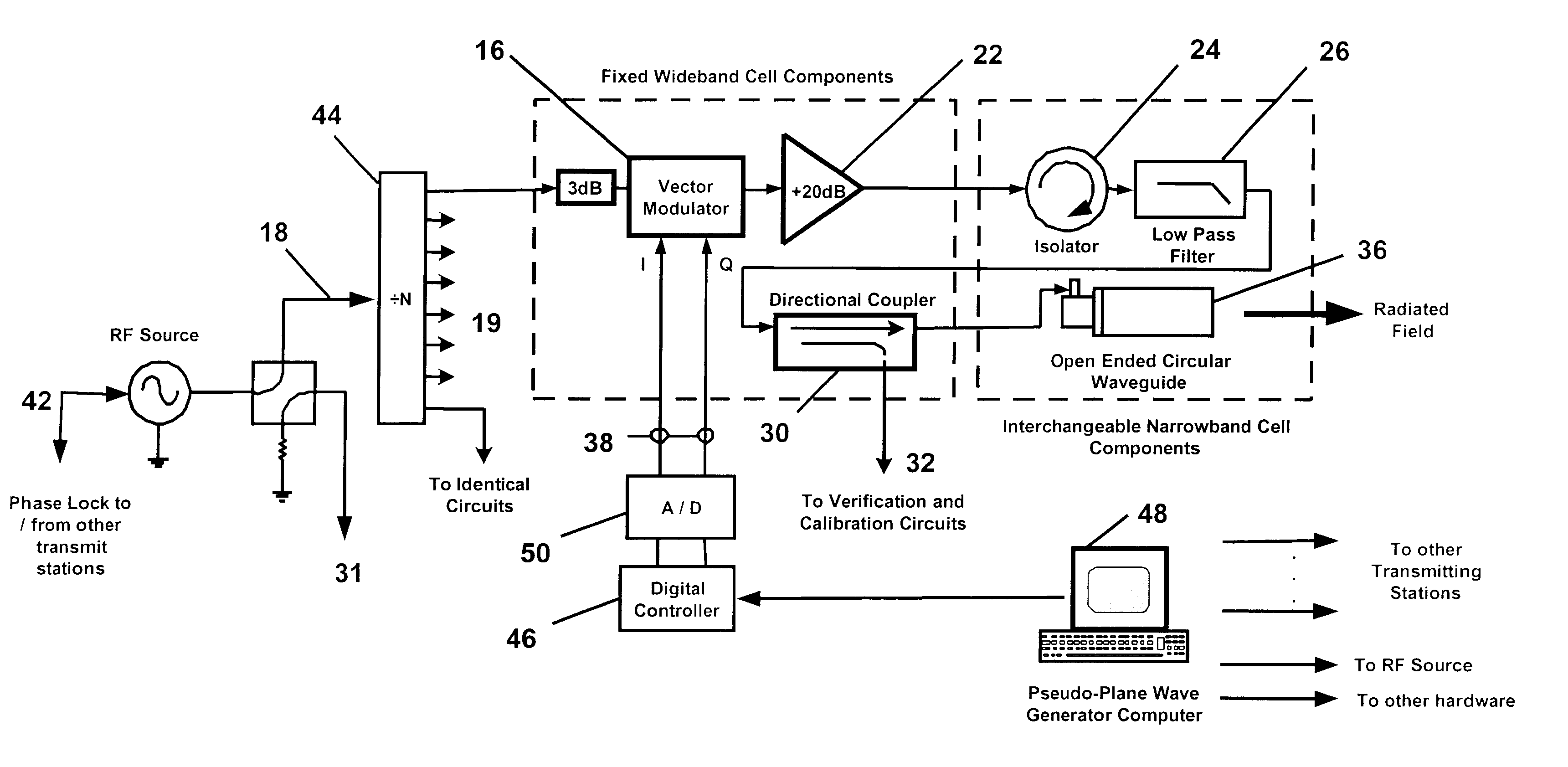
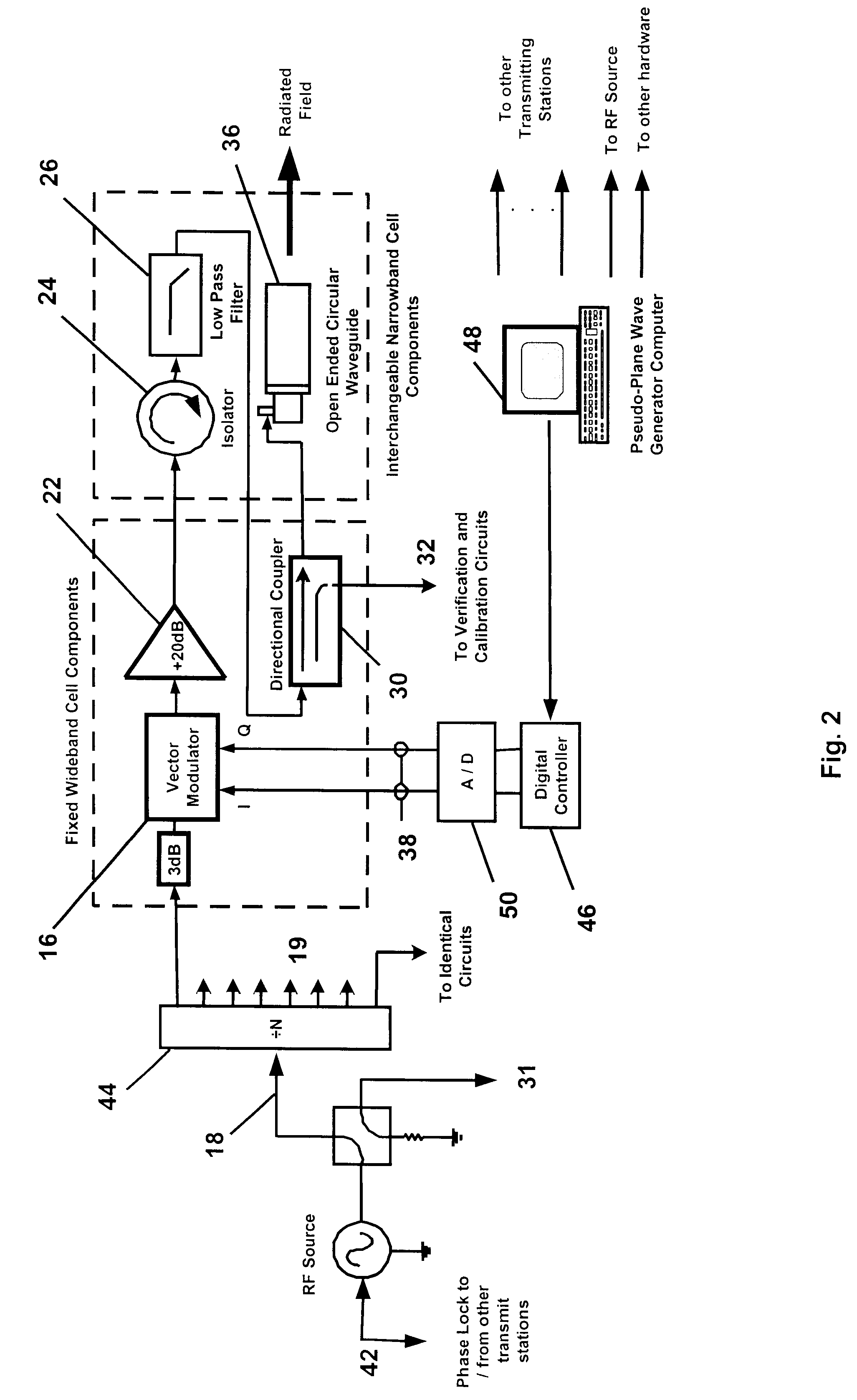
In general, the Pseudo-Plane Wave Generator produces a time harmonic electromagnetic environment in either the entire region, or specified subsets, of the OUT. The characteristics of this environment are such that measurements of the behavior of electronic circuits embedded within a large (many wavelengths in size) OUT and coupled in an electromagnetic sense to the exterior via small, relative to OUT size, distributed apertures and / or wire penetrations, can be made. In general one may also wish to create plane wave environments for other reasons than for measurement of the behavior of electronic circuits imbedded in the OUT. For example, the OUT may have one or more antennas that are physically separated, whose response under plane wave irradiation is to be measured. The standard way of making these measurements has been to place the OUT a large distance--the far field--from a radiating antenna. Specifically, the far field distance is greater than 2D.sup.2 / .lambda. where D=is the ...


PUM


Abstract

An apparatus and method for generating an electromagnetic environment in which the free field, plane wave response of electronic systems of an electrically large (greater than several wavelengths in its longest dimension) object, or objects, under test can be measured in the electromagnetic radiating near field of the transmitter array apparatus. The apparatus comprises: (1) one or more transmitting station(s), each station home to an array of radiating elements; (2) a software operating system and computer that controls the electronic circuits of the apparatus and executes an optimizing algorithm based on a Genetic Algorithm to control the radiation of each transmitting station; and (3) mechanical and electrical circuits that enable the apparatus to conduct self calibration and adjustment as required. In operation, the apparatus is placed and distributed about an object under test. With input from an operator, an optimization procedure based on a Genetic Algorithm determines the magnitude and phase of each radiating element, of each transmitting station. The apparatus then creates an electromagnetic environment that couples to sensors through small apertures distributed about the object under test, and causes the electronic behavior of electronic systems of the object under test to mimic their response to a true free field, plane wave environment.

Description

1. Field of the Invention (Technical Field)The Pseudo-Plane Wave Generator invention relates to measuring electronic circuit responses of large objects and more particularly to a distributed electronic and mechanical apparatus comprised of one or more stations of a radiating array that can generate an electromagnetic environment suitable for measurement of the circuit response of electrically large objects to free field, plane wave environments within the confines of a volume, like an anechoic chamber, that normally would not permit such a measurement due to the large distances normally associated with the creation of a true plane wave environment. The invention applies to a broad range of applications that utilize wavelike phenomena represented by the linear superposition principle, including, but not limited to sonar, audio, and optics applications.2. Background ArtTo measure the electronic circuit response of large objects (many wavelengths in extent at the frequency of operation...

Claims


Application Information

Patent Timeline
Patent Type & Authority Patents(United States)
IPC IPC(8): G01S7/40H01Q21/06
CPCG01S7/40H01Q21/06G01S7/4052G01S7/52004G01S2007/4086G01S7/497G01S7/4086
Inventor COURTNEY, CLIFTON C.VOSS, DONALD E.
Owner DONALD E VOSS D B A VOSS SCI
Why Eureka
Try Eureka