Electrical circuit for transmitting state information, in particular concerning rail rolling stock, and an electrical system incorporating such a circuit

a technology of state information and electrical circuit, which is applied in the direction of relays, pulse techniques, transportation and packaging, etc., can solve the problems of large amount of extra current, power consumption, and low-energy links of computer types unsuitable for this type of use, and achieve the effect of reducing power dissipation and high reliability

Inactive Publication Date: 2003-11-11
ALSTOM SA
View PDF7 Cites 9 Cited by
  • Summary
  • Abstract
  • Description
  • Claims
  • Application Information

AI Technical Summary

Benefits of technology

An object of the invention is thus to convey an item of information of the on / off type with a high degree of reliability and availability, while reducing the power dissipated by the Joule effect.

Problems solved by technology

For example, such signals are representative of the state of a circuit-breaker or of the open or the closed position of a door giving access to a carriage, and they must be conveyed with a high degree of security and availability, which makes low-energy links of the computer type unsuitable for this type of use.
The current is consumed and lost in the resistor.
However, currently the use of such fans as a mode of cooling the electronic circuits on board trains is avoided or even prohibited for reasons of reliability, since a fan includes mechanical components that might jam or seize and in general might fail.
As a result, to obtain the minimum current required for cleaning the switches, it must be accepted that a large amount of extra current and therefore power must be consumed during certain periods in the operation of the circuit.
The resulting additional production of heat increases the problem of removing said heat.

Method used


Image

  • Electrical circuit for transmitting state information, in particular concerning rail rolling stock, and an electrical system incorporating such a circuit
  • Electrical circuit for transmitting state information, in particular concerning rail rolling stock, and an electrical system incorporating such a circuit
  • Electrical circuit for transmitting state information, in particular concerning rail rolling stock, and an electrical system incorporating such a circuit

Examples


Embodiment Construction

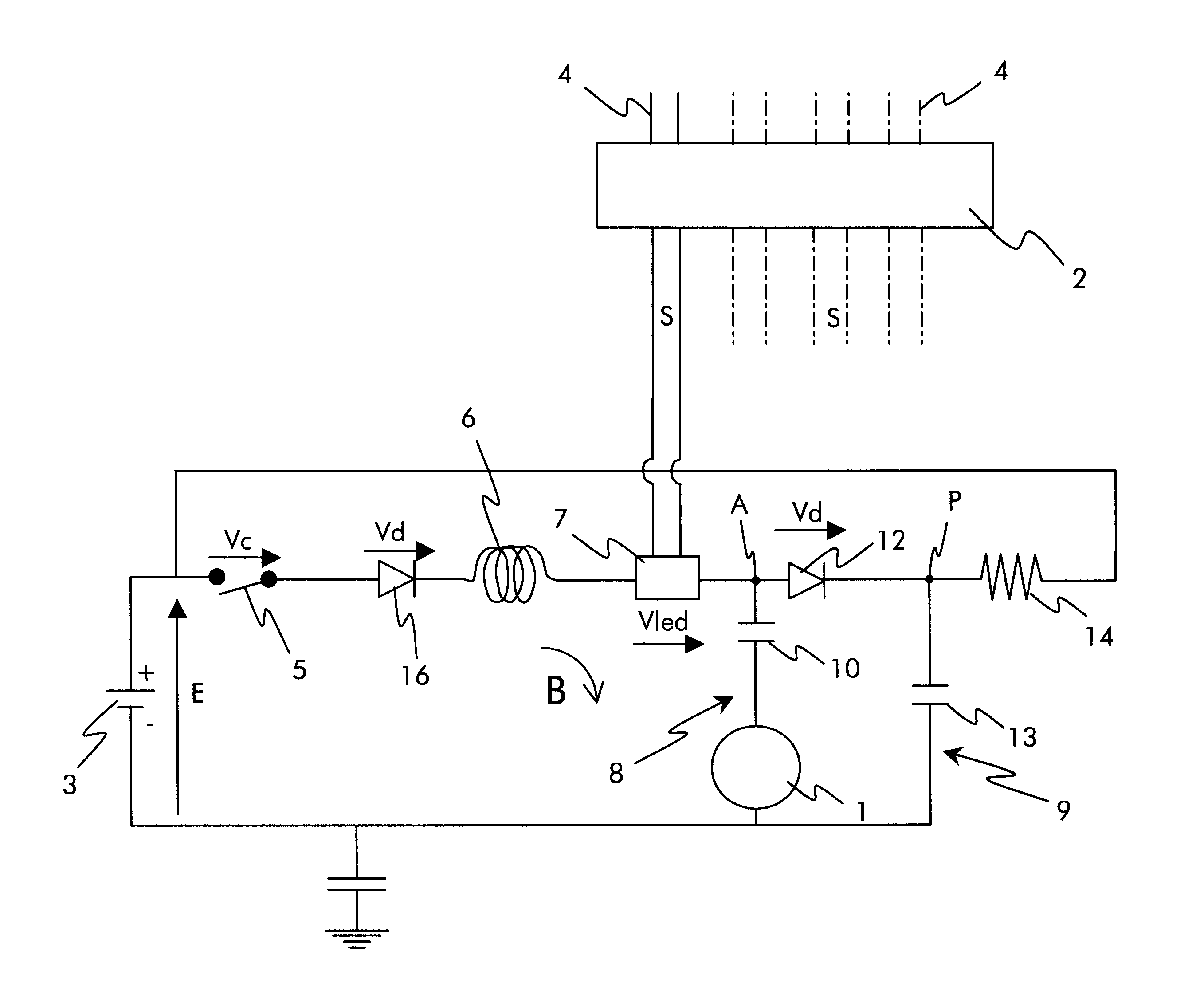
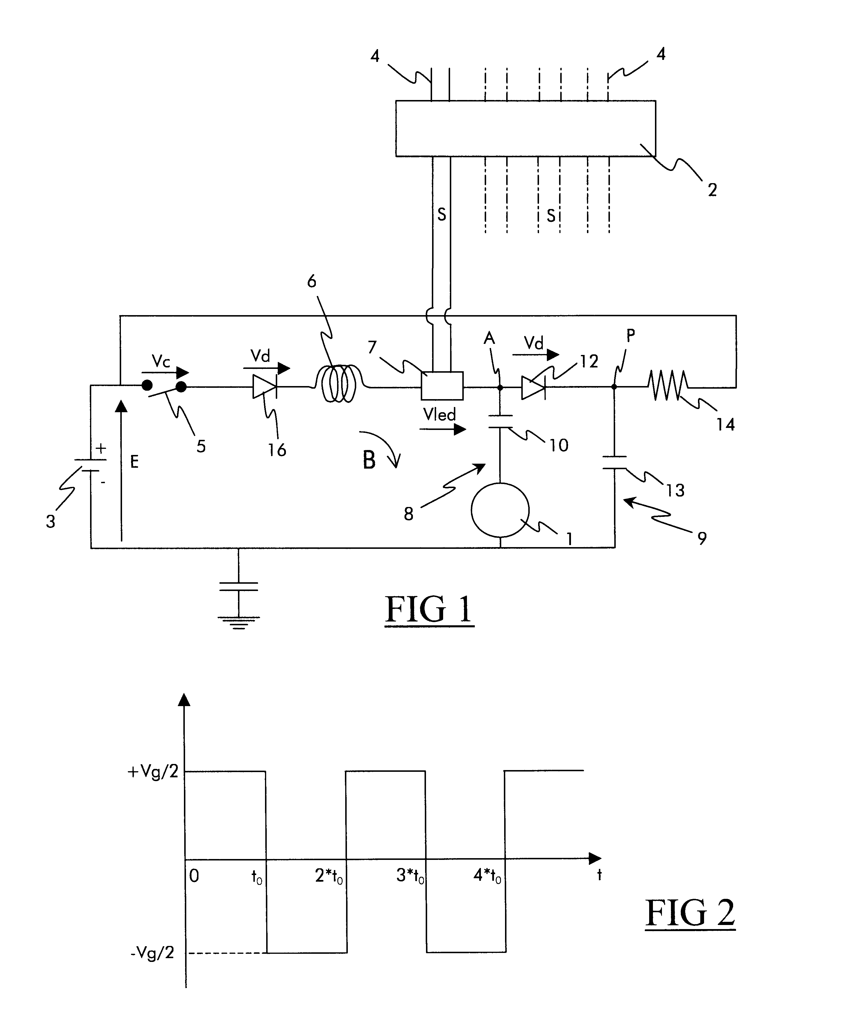
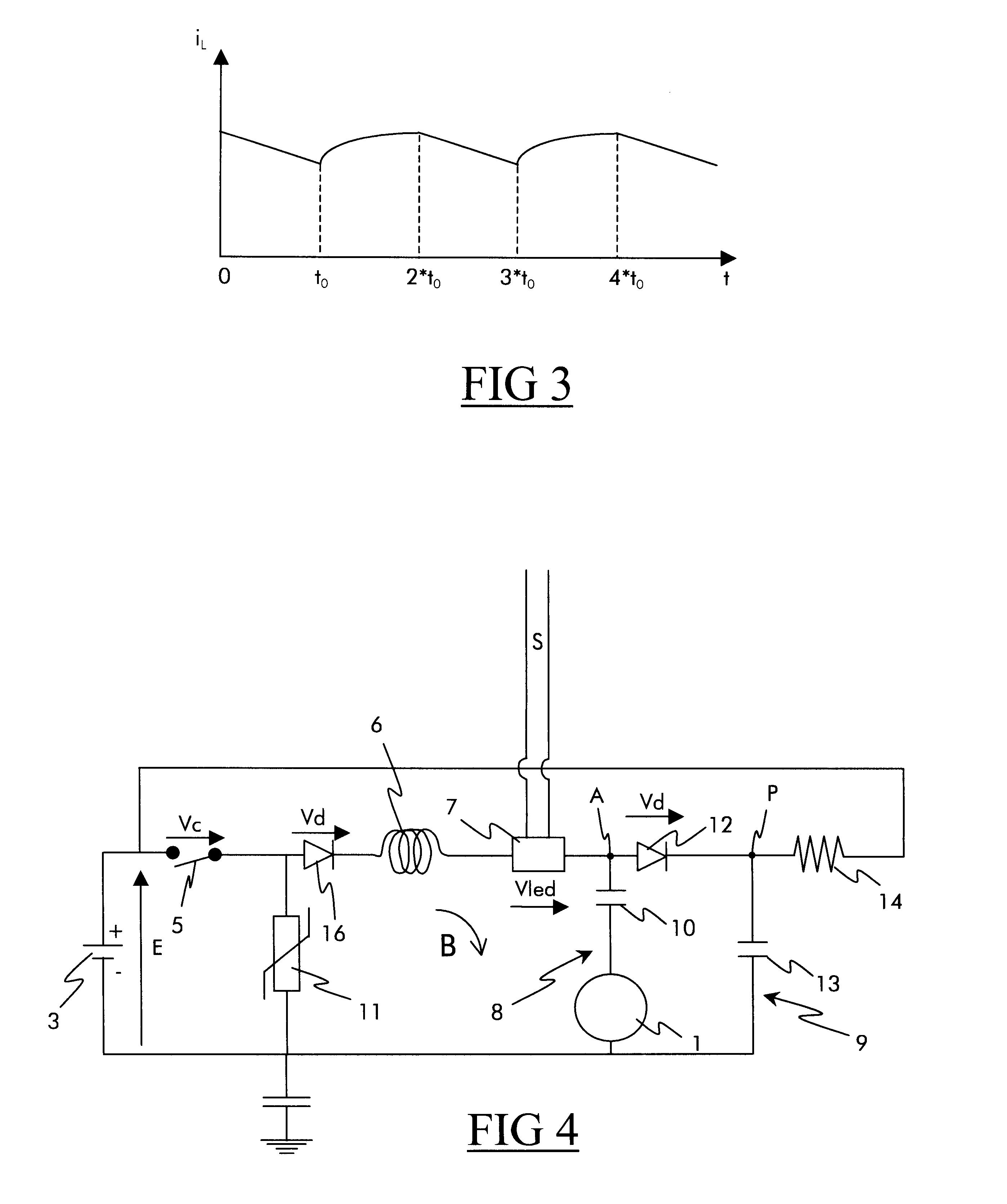
To make the drawings more legible, only those elements that are necessary to understand the invention are shown. Like elements bear like references from one figure to another.

FIG. 1 shows a particular embodiment of a transmission circuit suitable for transmitting an item of on / off information representative of the state of a member or of an item of equipment to be monitored, in particular rail vehicle equipment. FIG. 1 shows, on its own, an elementary circuit that is part of a fuller electrical system (not shown) comprising a plurality of similar elementary circuits connected in parallel across the terminals of a storage battery and suitable for transmitting a plurality of items of on / off information to an electronic circuit for controlling automatic logic controllers.

The electrical transmission circuit is connected across the terminals of a storage battery 3, and a connection S at the output of the elementary circuit retrieves the on / off information by means of a link which is desc...


PUM


Abstract

The invention relates to an electrical circuit for transmitting the state of a parameter or of an item of equipment, said electrical circuit being designed to be connected to the terminals of a power supply storage battery and comprising: an isolated link between said electrical circuit and an output (S) for transmitting an item of state information; and a switch whose open position or whose closed position is representative of the state information and which determines whether current flows through said electrical circuit, the electrical circuit transmitting the state information from the switch to the output via the isolated link. To regulate the magnitude of the current in the switch, the electrical circuit further comprises variable voltage generator means co-operating with switching means to power component elements of the electrical circuit selectively as a function of the output voltage of said variable voltage generator means, and wherein the electrical circuit further comprises inductive filter means in series with the switch, and capacitive storage means, each of which, under steady state conditions, forming energy-storage means and energy-yielding means for storing or yielding a portion of the energy of said electrical circuit, depending on the output voltage of the variable voltage generator.

Description

The invention relates to an electrical circuit for conveying information of the on / off type, in particular for use in the rail field.In a train, numerous signals of the on / off type indicating the state of a parameter or of an item of equipment are conveyed, for example to an electronic circuit for controlling automatic logic controllers or to a monitoring and signalling panel. For example, such signals are representative of the state of a circuit-breaker or of the open or the closed position of a door giving access to a carriage, and they must be conveyed with a high degree of security and availability, which makes low-energy links of the computer type unsuitable for this type of use.A solution that is currently used consists in connecting a closed-loop electrical circuit across the terminals of a storage battery, that circuit comprising, in series, at least one switch associated with the state of the member to be monitored, a resistor, and an isolated link connected to the device t...

Claims


Application Information

Patent Timeline
Patent Type & Authority Patents(United States)
IPC IPC(8): H01H1/60H01H1/00H01H9/16B61D37/00H03K17/78
CPCH01H9/167H01H1/605
Inventor BERT, MICHELCONVERT, PATRICK
Owner ALSTOM SA
Why Eureka
Try Eureka