Method and device for reducing crosstalk interference

a crosstalk interference and transmission system technology, applied in the field of digital data duplex transmission systems, can solve the problems of difficult to avoid twisted-pair wiring from all parts of the interconnecting transmission medium, inducing electromagnetic interference on each other, and data signals being transmitted over twisted-pair phone lines at high speeds can be significantly degraded, so as to reduce crosstalk interference and reduce the effect of crosstalk interference adaptively and improve speed

Inactive Publication Date: 2003-11-11
TELEFON AB LM ERICSSON (PUBL)
View PDF12 Cites 40 Cited by
  • Summary
  • Abstract
  • Description
  • Claims
  • Application Information

AI Technical Summary

Benefits of technology

An advantage of the present invention is that the computation of the estimated crosstalk interference is simple and rapid, thus permitting adaptive reduction of crosstalk interference in real time to accommodate, for example, changing transmitting

Problems solved by technology

It is difficult to avoid twisted-pair wiring from all parts of the interconnecting transmission medium.
However, within the binder, the twisted-pair phone lines, being located close together, induce electromagnetic interference on each other.
As a result, the data signals being transmitted over the twisted-pair phone lines at high speeds can be significantly degraded by the crosstalk caused by other twisted-pair phone lines in the binder.
As the speed of data transmission increases, the problem gets worse.
The difficulty with such conventional crosstalk cancelers is that they are very complex and consume large amounts of resources.
The document does not, however, address prob

Method used


Image

  • Method and device for reducing crosstalk interference
  • Method and device for reducing crosstalk interference
  • Method and device for reducing crosstalk interference

Examples


first embodiment

Sharing of Main Rotations among Coupling Factors Associated with a Single Disturbed Line

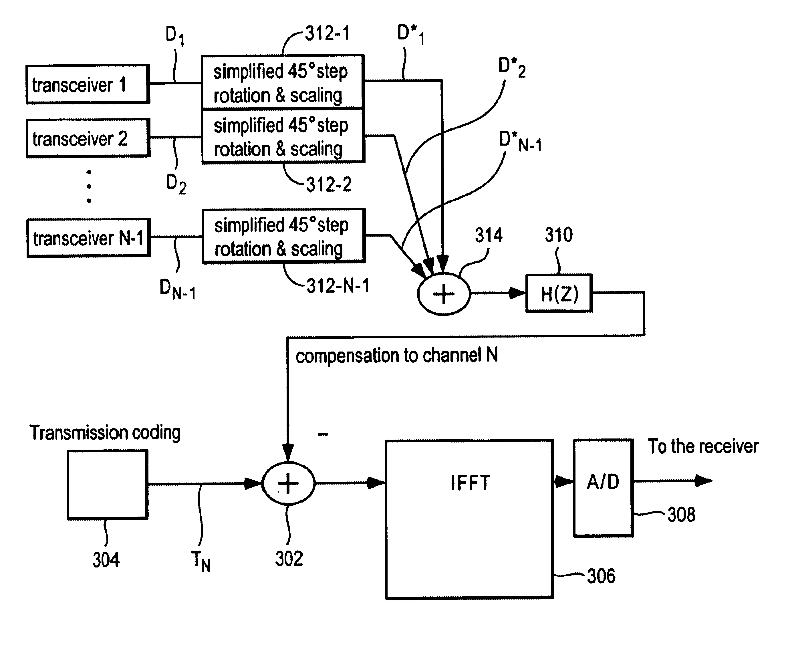
FIG. 3 shows, accordingly, a conceptual diagram of crosstalk reduction on a line according to a first embodiment of the present invention.

Compensation, i.e. crosstalk reduction, of a signal on a line or channel N is preferably introduced at 302, i.e. in the transmitter N after transmission coding 304, but before modulation by the fast inverse Fourier transform (IFFT) 306 and analog-to-digital conversion 308, where the signal still is in the frequency plane. Detailed descriptions of the principle of multitone modulation as such may be found in J. A. C. Bingham, Multicarrier modulation for data transmission: an idea whose time has come, IEEE Communications Magazine, May 1990, pp. 5-14, and in references therein.

The inventive concept is to reduce the number of complex multiplications by using a finite number of filters, i.e. predetermined fixed or adaptive filters. In FIG. 3 only one complex multipl...

second embodiment

Sharing of Main Rotations among Coupling Factors Associated with a Single Crosstalk Inducing Line

As described above a complex multiplication can be performed by a pre-rotation followed by a main rotation and a scaling. But, this is equivalent to perform the main rotation before the pre-rotation. Consequently, instead of sharing main vectors for a single disturbed line, sharing may be performed, according to a second embodiment of the present invention, by considering a single disturbing signal D.sub.j on a line j. This signal D.sub.j on line j has N-1 different associated coupling factors .alpha.'.sub.j.sub..sub.-- .sub.1, .alpha.'.sub.j.sub..sub.--.sub.2, . . . , .alpha.'.sub.j.sub..sub.-- .sub.j-1 .alpha.'.sub.j.sub..sub.-- .sub.j+1, . . . , .alpha.'.sub.j.sub..sub.--.sub.N for crosstalk interferences induced on lines 1, 2, . . . , j+1, . . . , N.

By grouping said coupling factors (according to their phases) into different sets, each set being. associated with a single specific mai...

third embodiment

CORDIC Rotation

According to a third embodiment (not shown in the Figures) of the present invention any of the two previously described embodiment may be combined with the use of a vector rotation method called CORDIC (COordinate Rotation DIgital Computer) for the main rotations.

CORDIC is an iterative method for performing vector rotation, see e.g. J. E. Volder, "The CORDIC trigonometric computing technique", IRE Trans. on Electron. Computers EC-8, pp. 330-334, September, 1959. In this method a number of simple rotations that may be performed by two additions / subtractions are used. The CORDIC rotations angles are + / -arctan(2.sup.-i), where i is a positive integer. A rotation may be written

RE.sub.n+1 =RE.sub.n -s.sub.i 2.sup.-i IM.sub.n

IM.sub.n+1 =IM.sub.n +s.sub.i 2.sup.-i RE.sub.n

Where RE is the real part and IM is the imaginary part of the vector to rotate and s.sub.i has the value +1 or -1 depending on the direction the rotation is made.

In hardware a CORDIC rotation is easy to acc...


PUM


Abstract

In a transmission system which makes use of frequency translated signals, said system having a plurality of lines, a method for reducing crosstalk induced on a signal on a first line of said plurality of lines by a signal on a second line of said plurality of lines, comprising estimating a complex coupling factor for the crosstalk, which when multiplied by the signal on the second line estimates the induced crosstalk; and subtracting the estimated induced crosstalk from the signal on the first line. The invention comprises an approximation method for multiplying the complex coupling factor by the signal on the second line that operates on the signal on the second line through pre-rotation, scaling and multiplication by a complex number according to the coupling factor, said complex number being chosen from a bank of predetermined complex numbers so as to obtain the best approximation possible.

Description

The present invention relates to a method and a device for reducing crosstalk interference in a transmission system which makes use of frequency translated signals, particularly a discrete multi tone (DMT) modulated transmission system or an OFDM (Orthogonal Frequency Division Multiplex) transmission system, in. which the modulation may be effected using a fast inverse Fourier transform (IFFT). The invention relates further to the transmission system itself, and to a transceiver of said transmission system.DESCRIPTION OF RELATED ARTDigital data duplex transmission systems are currently being developed for high-speed communication. Standards for high-speed data communication over twisted-pair phone lines that have been developed include Asymmetric Digital Subscriber Lines (ADSL) and Very High Speed Digital Subscriber Lines (VDSL).A standardized ADSL system (ANSI T1.413-1995, ATIS Committee T1E1.4), providing transmission at rates up to 8 Mbit / s over twisted-pair phone lines, defines ...

Claims


Application Information

Patent Timeline
IPC IPC(8): H04B3/46H04B1/10H04J11/00H04B3/06H04B3/32
CPCH04B3/487H04L27/26
Inventor HJELM, MIKAELRUDBERG, MIKAEL
Owner TELEFON AB LM ERICSSON (PUBL)
Why Eureka
Try Eureka