
Friction stir welding using a superabrasive tool

a technology of friction stir welding and superabrasive material, which is applied in the direction of manufacturing tools, soldering devices, auxillary welding devices, etc., can solve the problems of compromising welds, no tool that is capable of functional welding materials having higher melting points, and non-metallic reinforcement materials which have been joined with original workpiece materials to create alloys, etc., to achieve the effect of improving wear characteristics

Inactive Publication Date: 2003-11-18
BRIGHAM YOUNG UNIV +1
View PDF73 Cites 154 Cited by
  • Summary
  • Abstract
  • Description
  • Claims
  • Application Information

AI Technical Summary

Benefits of technology

It is an object of the present invention to provide a new tool for use in friction stir welding that has improved wear characteristics over conventional tools.
In a tenth aspect of the invention, the superabrasive coating is selected based upon the characteristic of having a low coefficient of friction that prevents the workpiece material from adhering to the tool, thereby reducing wear of the tool.

Problems solved by technology

Thus, while friction stir welding is a very advantageous technique for welding non-ferrous alloys such as aluminum, brass and bronze, there has been no tool that is capable of functionally welding materials having higher melting points.
Unfortunately, fusion welding alters or damages the alloy at the weld, thereby compromising the weld as a result of the defects or adverse phases which form in the weld during the welding process.
In some cases, the non-metallic reinforcement material which has been joined with the original workpiece material to create the alloy is depleted at the weld.
Most tools simply do not work at all in MMCs, ferrous alloys, and superalloys.
If a conventional tool could begin friction stir welding, the wear would be so significant that a probe would be torn apart after only a short distance.
For example, some alloys will cause wear on a probe such that it can no longer function after welding for a distance of only inches.
Unfortunately, it is generally the case that it is not possible to simply insert a new tool and begin the friction stir welding process where the previous probe failed.
If the weld is not continuous and uninterrupted, it is useless because of mechanical weakness.
Furthermore, a portion of the tool is typically left behind in the workpiece material, also contributing to the mechanical weakness.
MMCs have desirable stiffness and wear characteristics, but they also have a low fracture toughness, thereby limiting applications.
There are significant challenges that have so far prevented the creation of a tool that can functionally weld MMCs, ferrous alloys, and superalloys.

Method used


Image

  • Friction stir welding using a superabrasive tool
  • Friction stir welding using a superabrasive tool
  • Friction stir welding using a superabrasive tool

Examples


Embodiment Construction

Reference will now be made to the drawings in which the various elements of the present invention will be given numerical designations and in which the invention will be discussed so as to enable one skilled in the art to make and use the invention. It is to be understood that the following description is only exemplary of the principles of the present invention, and should not be viewed as narrowing the claims which follow.

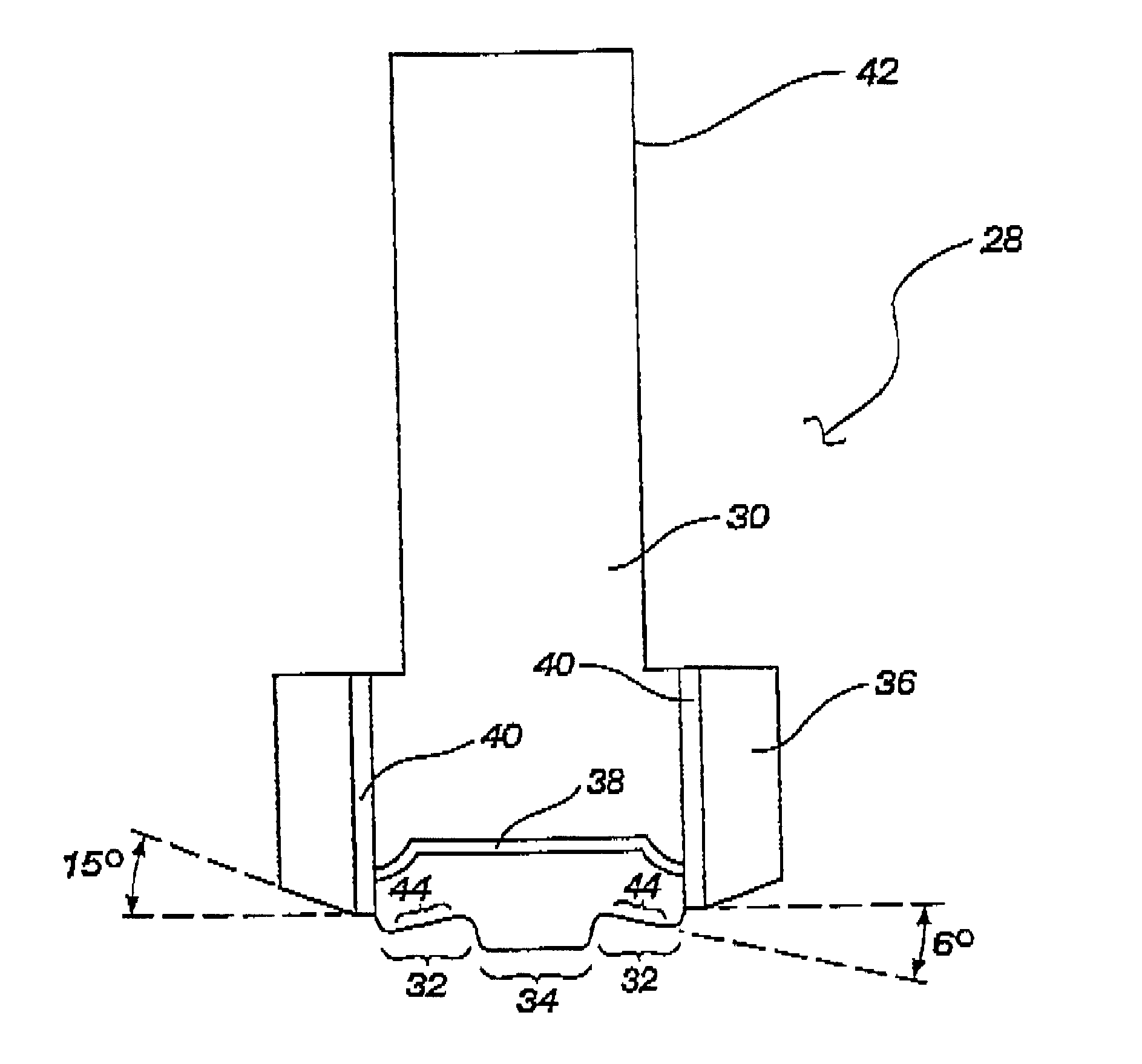
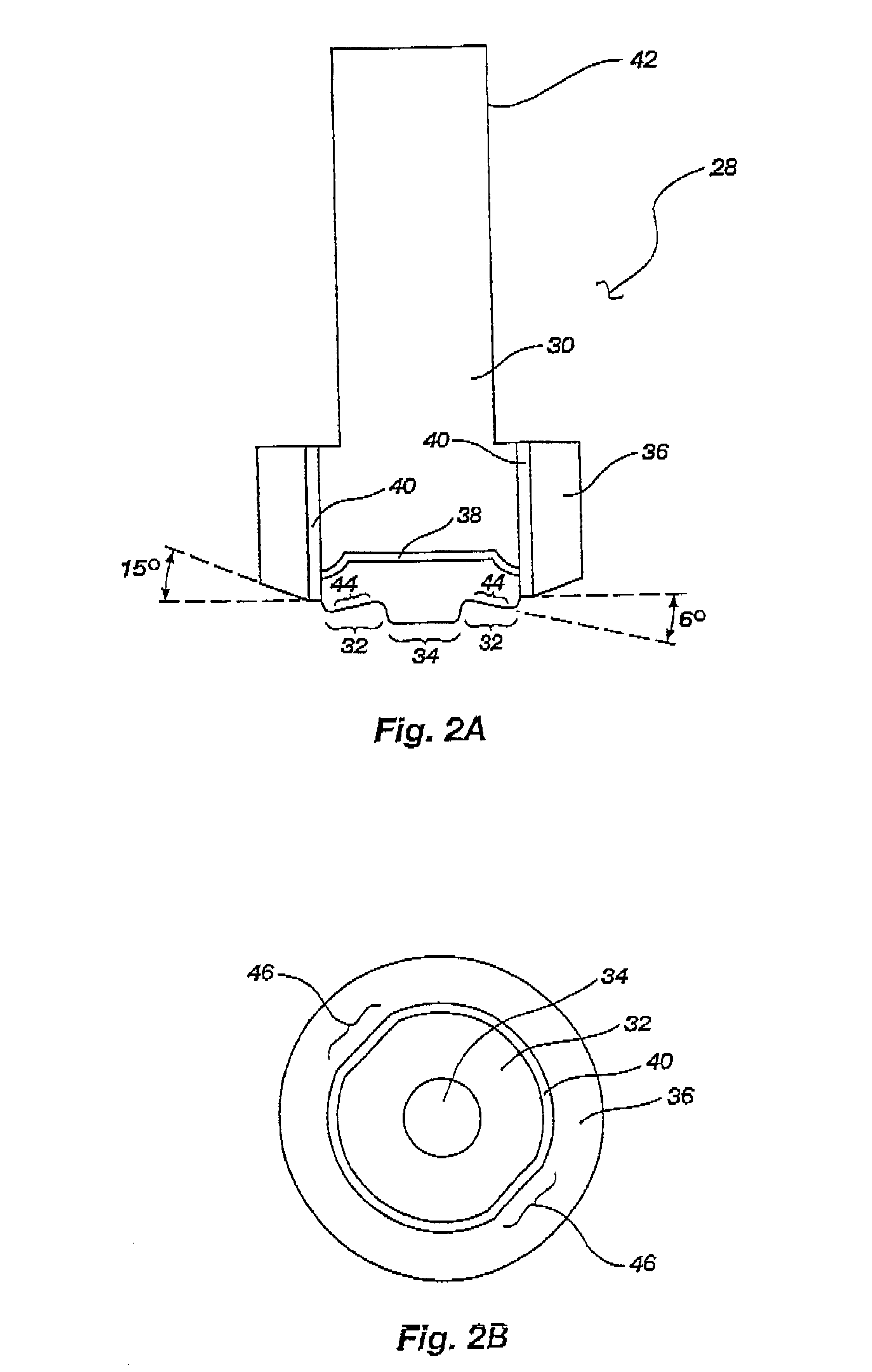
The presently preferred embodiment of the invention is a tool that incorporates superabrasive materials in a pin and shoulder, and utilizes thermal management within the tool, to enable friction stir welding of materials that are presently functionally unweldable. Thus, the present invention makes possible long, continuous, and uninterrupted welds of MMCs, ferrous alloys, and superalloys without suffering significant degradation of the tool.

The development of the presently preferred embodiment presented significant challenges because conventional tools wore out o...


PUM

PropertyMeasurementUnit
temperatureaaaaaaaaaa
diameteraaaaaaaaaa

Abstract

A probe for friction stir welding MMCs, ferrous alloys, non-ferrous alloys, and superalloys, as well as non-ferrous alloys, the probe including a shank, a shoulder, and a pin disposed through the shoulder and into the shank, wherein the pin and the shoulder at least include a coating comprised of a superabrasive material, the pin and shoulder being designed to reduce stress risers, disposing a collar around a portion of the shoulder and the shank to thereby prevent movement of the shoulder relative to the shank, and incorporating thermal management by providing a thermal flow barrier between the shoulder and the shank, and between the collar and the tool.

Description

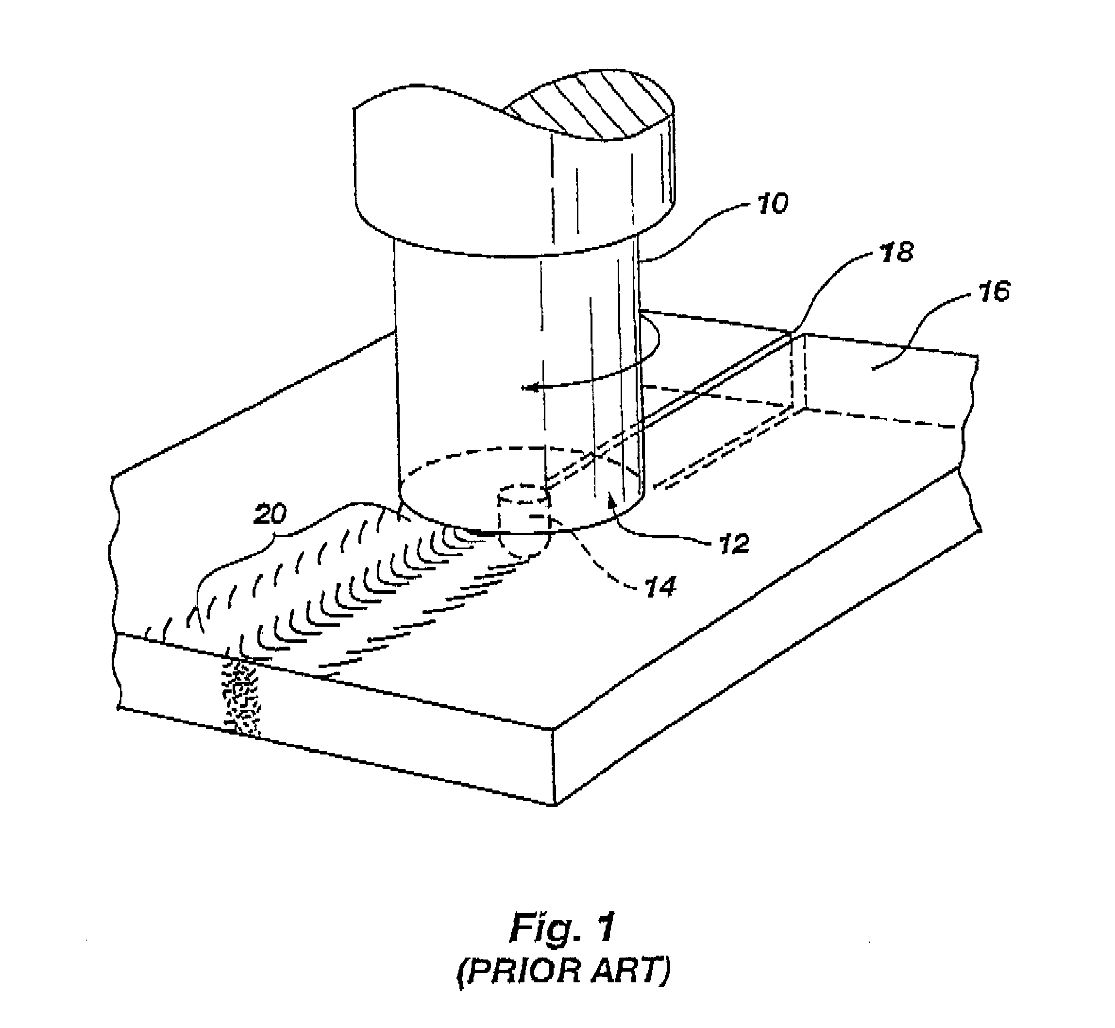
BACKGROUND1. The Field of the InventionThis invention relates generally to friction stir welding wherein heat for creating a weld is generated by plunging a rotating pin of a tool into a workpiece. More specifically, the present invention relates to a new tool that is used in a friction stir welding process that enables the present invention to weld materials that are not functionally weldable using state of the art friction stir welding processes and tools, said materials including ferrous alloys such as stainless steel, and higher melting point super alloys that contain only small amounts of or no ferrous materials at all.2. Background of the InventionFriction welding has been used in industry for years. It is a solid-state process that yields large economic benefits because it avoids many problems associated with rapid solidification of molten material that occurs in traditional fusion welding processes.One example of friction welding occurs when the ends of two pipes are pressed...

Claims


Application Information

Patent Timeline
Patent Type & Authority Patents(United States)
IPC IPC(8): B23K20/12B23K20/227B23K20/22C23C14/06
CPCB23K20/122B23K20/1255B23K20/129B23K20/227B23K2203/16B23K2203/04B23K2203/10B23K2101/006B23K2103/05B23K2103/04B23K2103/10B23K2103/16B23K20/12
Inventor NELSON, TRACEY W.SORENSEN, CARL D.PACKER, SCOTTFELTER, PAUL ALLEN
Owner BRIGHAM YOUNG UNIV
Learn More