Energy-efficient, finned-coil heat exchanger

a heat exchanger and finned coil technology, which is applied in indirect heat exchangers, lighting and heating apparatus, heating types, etc., can solve the problems of reducing the overall volume of the unit, and reducing the actual time during which cooler air is in contact with hotter refrigerant tube surfaces

Inactive Publication Date: 2003-12-09
KALE HEMANT D
View PDF15 Cites 14 Cited by
  • Summary
  • Abstract
  • Description
  • Claims
  • Application Information

AI Technical Summary

Problems solved by technology

This decreases resistance to the air movement, but enormously reduces the actual time during which cooler air is in contact with the hotter refrigerant tube surface.
However, the temperature rise of the air passing over the fins through the heat exchanger is typically only about 10.degree. F., about one-third of the maximum available.
Another problem with prior art finned-coil heat exchangers is that the general "slab" shape necessitates larger overall volume of the unit.
It therefore has a larger footprint, so it occupies more floor space.
Additionally, with a large surface area of the coil relative to the sweep of the fan blades, uneven air flow over the coil is created.
Because of this, excessive amounts of air pass through the coil surface that is closest to the fan, while the peripheral areas of the coil are starved.
This fac...

Method used


Image

  • Energy-efficient, finned-coil heat exchanger
  • Energy-efficient, finned-coil heat exchanger
  • Energy-efficient, finned-coil heat exchanger

Examples


Embodiment Construction

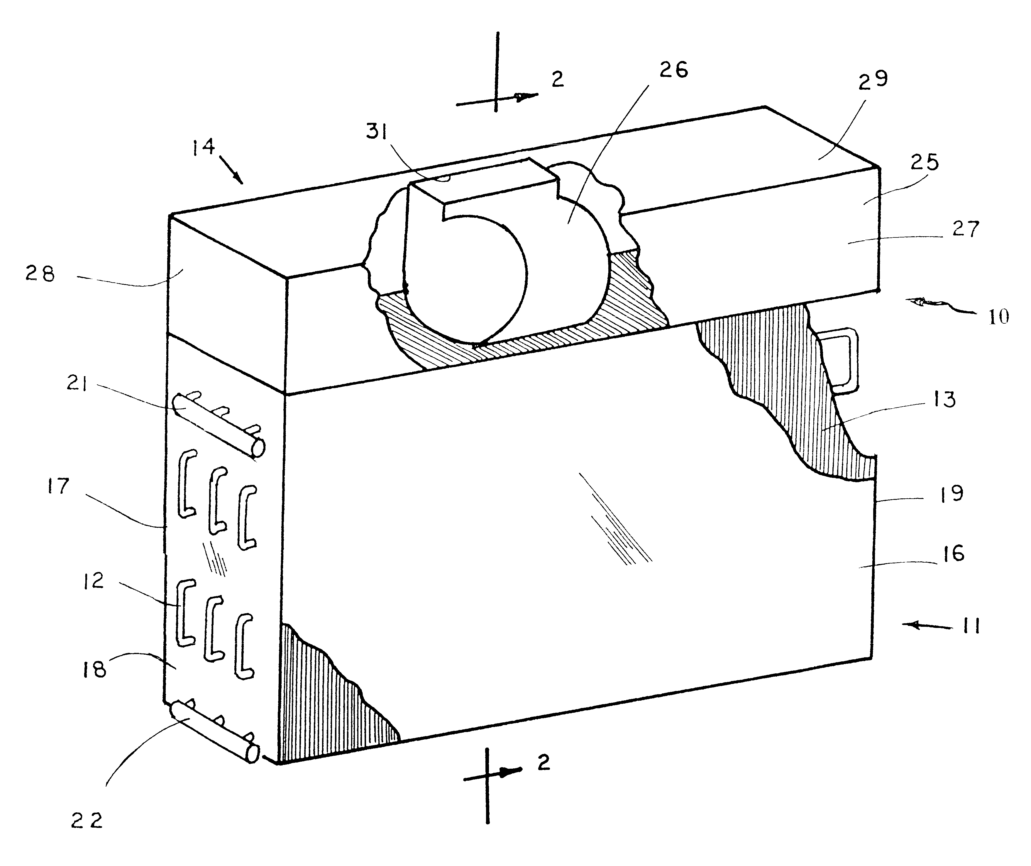
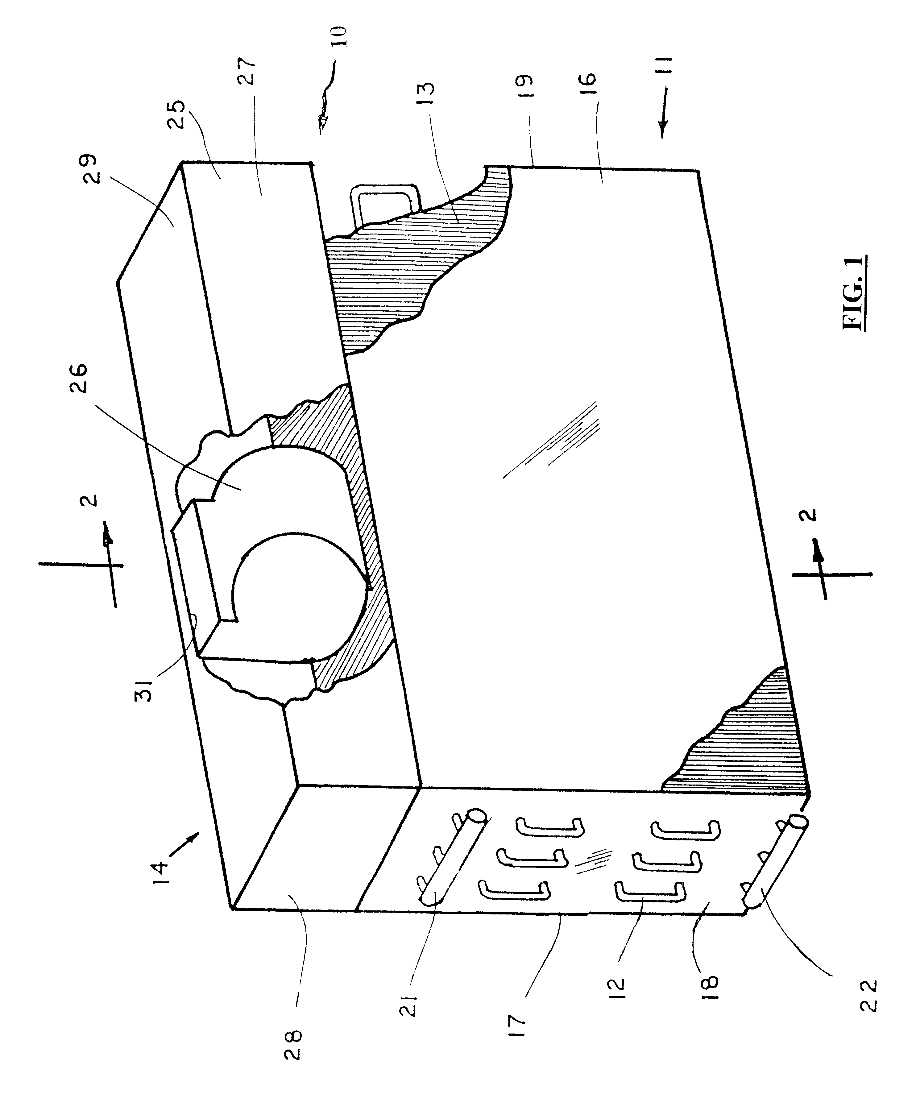
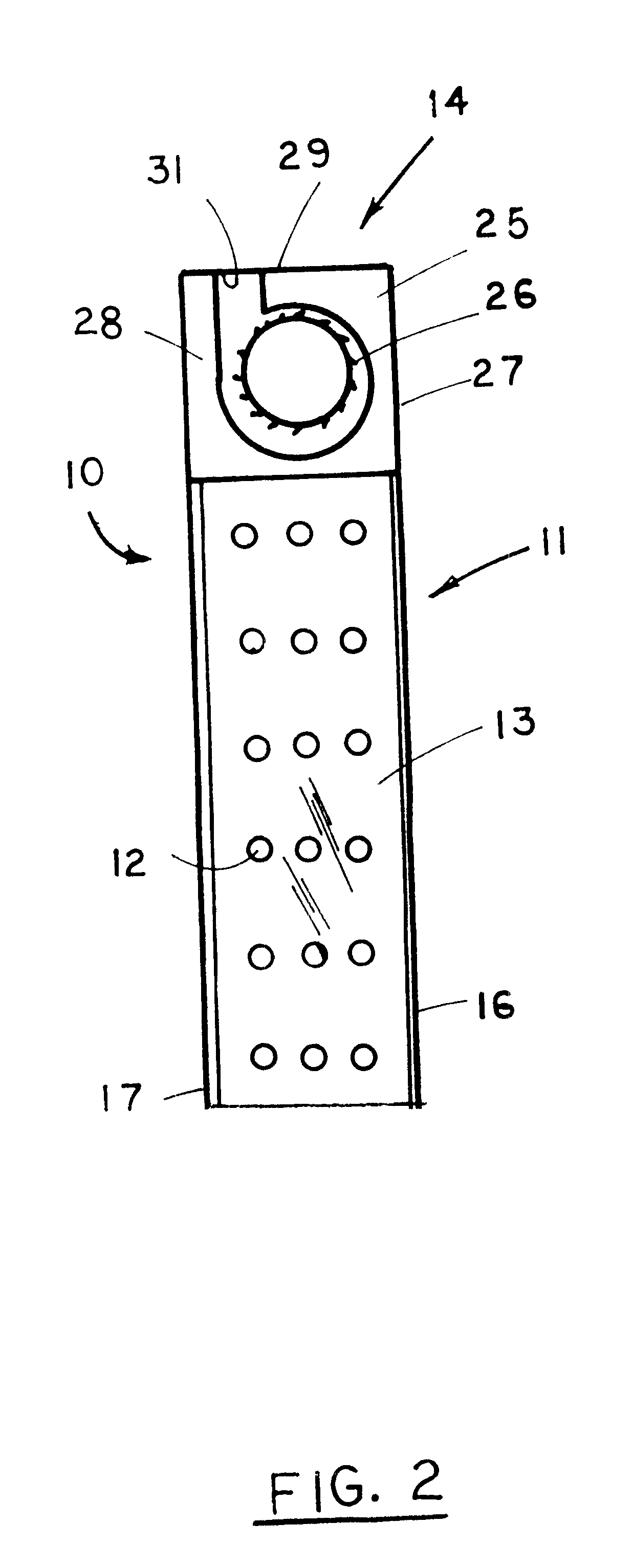
Referring to FIGS. 1 and 2 of the drawings, a heat exchanger, generally designated 10, for transferring heat from fluid to air broadly includes a housing, generally designated 11, a plurality of heated fluid conducting tubes, collectively designated 12, a series of spaced parallel heat transfer fins, collectively designated 13, and a fan unit, generally designated 14.

The rectilinear housing 11 is defined by spaced front and back walls 16 and 17, respectively, and laterally spaced side walls 18 and 19, respectively, which together define an internal heat exchange chamber area (not numbered). The open top and bottom of the housing 11 provide an inlet and an outlet for the internal chamber area. The front and back walls 16 and 17 define the vertical height and horizontal width of the housing 11 and the side walls 18 and 19 define the depth of the housing 11. As seen in FIG. 1, the housing 11 has a height greater than its depth. The housing 11 has an open upper end (not numbered) from w...


PUM


Abstract

A finned-coil heat exchanger has a housing with spaced walls defining an internal chamber with air flowing from an upstream end to a downstream end, spaced transfer tubes with heat conducting media flowing therein from the downstream chamber end to the upstream chamber end, a series of spaced fins in contact with the tubes to transfer heat to flowing air, and a fan unit to move air through the exchanger. An air inlet is defined at the upstream end of the housing or in the lower end of one of the walls so that air can enter the internal chamber. The tubes each extend tortuously back and forth on a plane parallel to the direction of air flow so that there is a counterflow effect across the various segments of each tube. The tubes have at least six segments extending transversely across air flow with the tubes and fins being sized and spaced to provide for better air flow through the heat exchanger housing.

Description

1. Technical FieldThis invention relates generally to heat exchangers and, more particularly, to a heat rejecting refrigerant-to-air finned coil heat exchanger used as a condenser in refrigeration and air conditioning devices.2. Background ArtHeat transfer is a function of available temperature difference and of time. The larger the temperature difference, the faster the heat transfer. However, for the same degree of available temperature difference, heat transfer can be increased by allowing longer real time contact between the two heat exchanging media. Complete heat transfer can be assured at all times by allowing an appropriate duration that heat exchanging media stay in contact.In the prior art, finned-coil heat exchangers using forced air are common. These exchangers always approached the shape of a slab, i.e., a large surface area with a very thin depth. This "slab" is often bent to form a "U-shape". Generally, the length dimension or width dimension or both of the coil surfa...

Claims


Application Information

Patent Timeline
IPC IPC(8): F24F1/00F28F1/32F28D1/047F28D1/04F25B39/04F24F1/0067
CPCF24F1/0059F28F1/32F28D1/0477F25B39/04F28D2001/0266F24F1/0067
Inventor KALE, HEMANT D.
Owner KALE HEMANT D
Why Eureka
Try Eureka