Hydrogen extraction unit

a technology of hydrogen extraction and unit, applied in the direction of colloidal chemistry, separation process, membrane, etc., can solve the problem of not much consideration so far

Inactive Publication Date: 2003-12-09
TOYOTA JIDOSHA KK
View PDF21 Cites 77 Cited by
  • Summary
  • Abstract
  • Description
  • Claims
  • Application Information

AI Technical Summary

Problems solved by technology

However, not much consideration has been given so far to a method of connecting the flow channel constituting members and the hydrogen separation film when laminating them as described above.

Method used


Image

  • Hydrogen extraction unit
  • Hydrogen extraction unit
  • Hydrogen extraction unit

Examples


modification example 2

G2.

Although the hole portions formed in the metal plate members are formed by etching in the aforementioned embodiments, they may also be formed by electric discharge machining (e.g., wire cut), laser machining, or press working. As long as the hole portions can be processed with acceptable precision, any method can be adopted.

modification example 3

G3.

Although the hydrogen separation plates are formed of self-supported films made of metal foil having the function of separating hydrogen, it is also appropriate that the hydrogen separation plates be constructed by forming a metal having the function of separating hydrogen (hereinafter referred to as the hydrogen separation metal) on thin porous base materials. By forming the hydrogen separation metal on the metal porous base materials, it becomes possible to enhance the rigidity of the hydrogen separation plates. In such a case as well, the effect of making the unit compact can be achieved by bonding the thin metal plate members together by a bonding method free from fusion of the base materials.

It is to be noted herein that various methods can be adopted as a method of forming the hydrogen separation metal on the porous base materials. For example, it is appropriate that the surfaces of the porous base materials be coated with the hydrogen separation metal by means of plating, ...

modification example 4

G4.

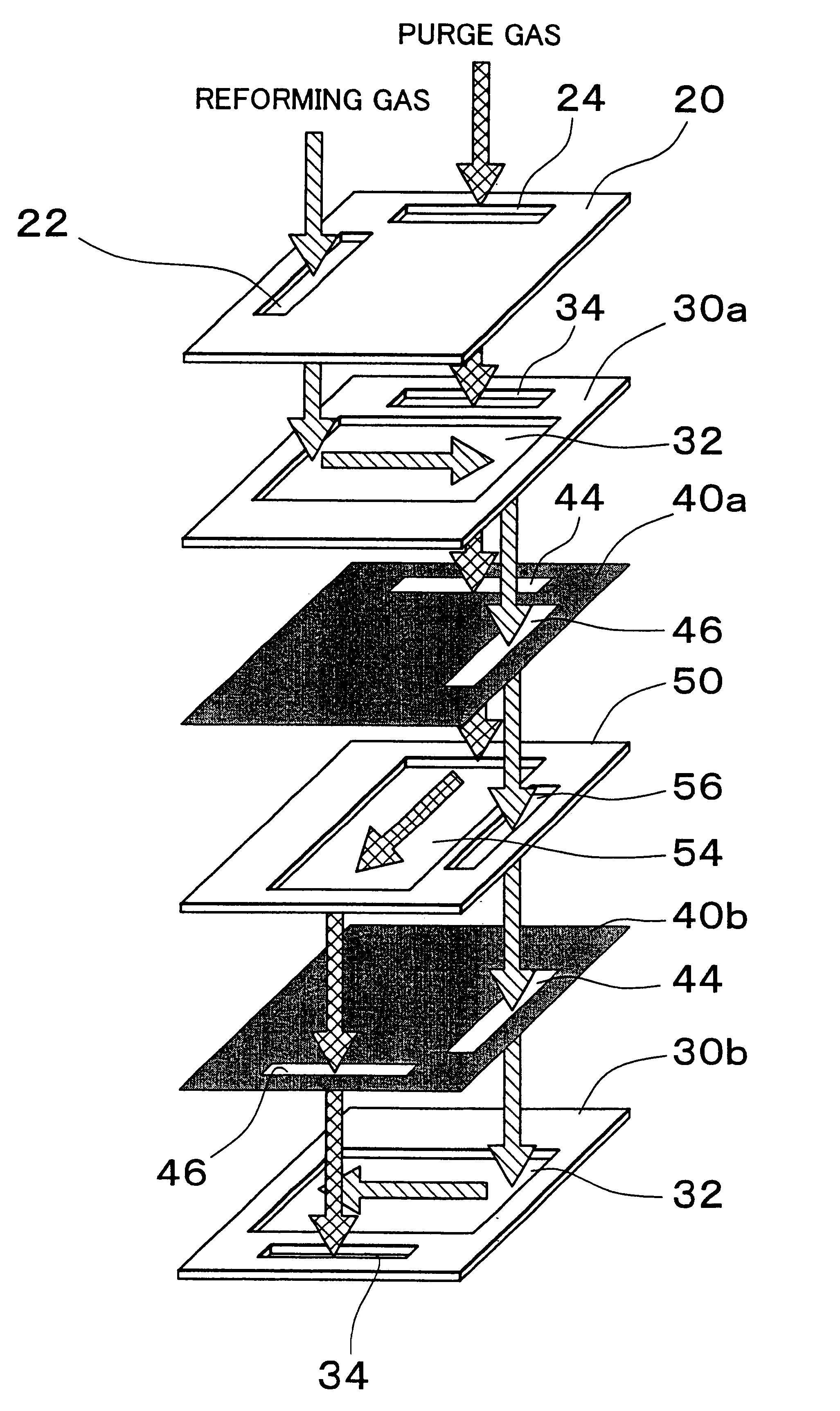
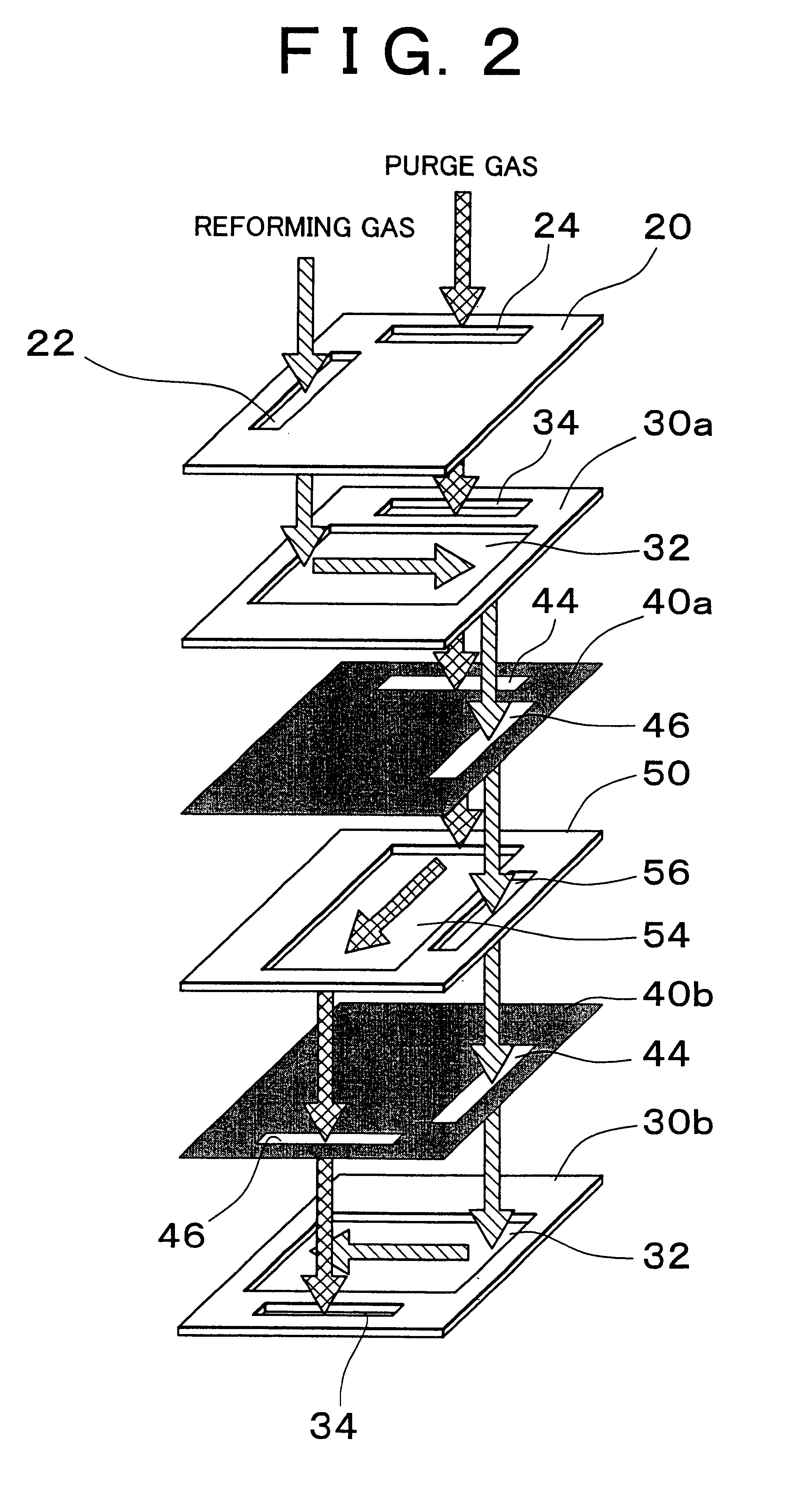
Although the gas flow channels contiguous to the hydrogen separation films are constituted by the hole portions (the gas flow channel holes) formed in the reformed gas flow channel plates and the purge gas flow channel plates in the aforementioned embodiments, the structure for forming the gas flow channels (the gas flow channel constituting portion) can be constructed differently. Instead of forming the hole portions in the aforementioned gas flow channel plates, it is also appropriate that a predetermined convexo-concave structure be formed on the surface of each of the gas flow channel plates and that a gas flow channel be formed between the convexo-concave structure and a corresponding one of the hydrogen separation films. In such a case as well, desired convexo-concave structures can be formed on the metal plates by etching with high precision.


PUM

PropertyMeasurementUnit
thicknessaaaaaaaaaa
thicknessaaaaaaaaaa
thicknessaaaaaaaaaa

Abstract

A hydrogen extraction unit has reformed gas flow channel plates, hydrogen separation plates, and purge gas flow channel plates, which are designed as thin metal plate members. The hydrogen extraction unit is constructed by laminating these thin plate members and then bonding them together by diffusion bonding. Each of reformed gas flow channel holes formed in the reformed gas flow channel plates constitutes a flow channel for reformed gas together with a correspondingly adjacent one of the hydrogen separation plates. Each of purge gas flow channel holes formed in the purge gas flow channel plates constitutes, together with a correspondingly adjacent one of the hydrogen separation plates, a flow channel for purge gas with which hydrogen extracted from reformed gas is mixed.

Description

1. Field of the InventionThe invention relates to a hydrogen extraction ( / separation) unit for extracting hydrogen from a hydrogen-containing gas that contains hydrogen2. Description of the Related ArtAs a unit for extracting hydrogen from a hydrogen-containing gas, there has been known a unit making use of a hydrogen separation film including a metal that selectively allows penetration of hydrogen (e.g., palladium or a palladium alloy). Such a hydrogen extraction unit is employed, for example, in a fuel cell system having a fuel cell.A fuel cell is designed to be supplied with fuel gas containing hydrogen and to obtain an electromotive force by an electrochemical reaction. As a method of applying a hydrogen extraction unit to a fuel cell system, it has been known to extract hydrogen from reformed gas (hydrogen-rich gas) obtained by reforming a hydrocarbonic fuel by means of the hydrogen extraction unit and to supply a fuel cell with the hydrogen thus obtained. In the hydrogen extra...

Claims


Application Information

Patent Timeline
Patent Type & Authority Patents(United States)
IPC IPC(8): B01D53/22C01B3/50C01B3/00
CPCB01D53/22B01D53/225B01D63/08C01B3/505C01B3/501B01D2257/108B01D2313/42Y10S55/05C01B2203/0405C01B2203/047C01B2203/0475
Inventor SATO, HIROMICHIIGUCHI, SATOSHIAOYAMA, SATOSHIITO, NAOKINAKATA, TOSHIHIDE
Owner TOYOTA JIDOSHA KK
Why Eureka
Try Eureka