Device for joining a panel and a structure, able to transmit significant forces

a technology of significant forces and joints, applied in mechanical devices, couplings, transportation and packaging, etc., can solve the problems of long and difficult implementation of known techniques, difficult installation of joint plates through the inside of wings, and difficulty in applying assembly techniques, so as to preserve the aerodynamic properties of the panels and reduce the phenomenon of delamination of this material

Inactive Publication Date: 2003-12-16
AIRBUS OPERATIONS (SAS)
View PDF24 Cites 34 Cited by
  • Summary
  • Abstract
  • Description
  • Claims
  • Application Information

AI Technical Summary

Benefits of technology

As will be seen in greater detail subsequently, for a given number of mounts, of identical dimensions, this arrangement makes it possible to increase, in the panel, the quantity of material between two adjacent nuts and, consequently, to increase the flux of forces able to be transmitted by the joint device.
To advantage, each cylinder then includes a countersunk head, housed in a complementary cavity formed on an outer surface of the panel, in such a way that an end surface of said head is flush with said outer surface. This arrangement makes it possible particularly to preserve the aerodynamic properties of the panel, in aerospace applications.
In this case, each cylinder also includes, preferably, a threaded end onto which is screwed a second nut supported on an inner surface of the panel. This arrangement is particularly advantageous in the event of the panel being made of composite material. Indeed it makes it possible to reduce the phenomena of delamination of this material, which could be caused by applying tensile / compressive forces essentially through the cylinders in which the nuts are mounted.

Problems solved by technology

However, this known technique is long and tricky to implement, particularly since it requires great precision of the bores, into which the mount components are received.
Moreover, the excess thickness due to the presence of the joint plate may, in certain cases, pose problems of assembly (for example during the assembly of two elements of a thin wing: the small distance between the lower surface and the upper surface then makes it difficult to install a joint plate through the inside of the wing), or of aerodynamics (for example in the case of a joint plate mounted on the outer surface of a wing).
However this assembly technique may be difficult to apply when one of the panels is made of a composite material.
Indeed, machining deep juxtaposed cut-outs near the panel edge would make the latter lose a major part of its mechanical strength in this area.
However, it does not make it possible to transmit between the two parts all the forces which the structural elements could withstand if they were not weakened by the device, as shown in FIG. 1 of the appended drawings.
This leads to an embrittlement of the panel, which may then tear approximately along the line formed by the holes.
Consequently, the joint device described in the document U.S. Pat. No. 5,171,099 is not adapted when the forces, which have to be able to be transmitted through it, exceed the maximum flux F.sub.0, as is the case in certain applications, particularly in aeronautics.

Method used


Image

  • Device for joining a panel and a structure, able to transmit significant forces
  • Device for joining a panel and a structure, able to transmit significant forces
  • Device for joining a panel and a structure, able to transmit significant forces

Examples


first embodiment

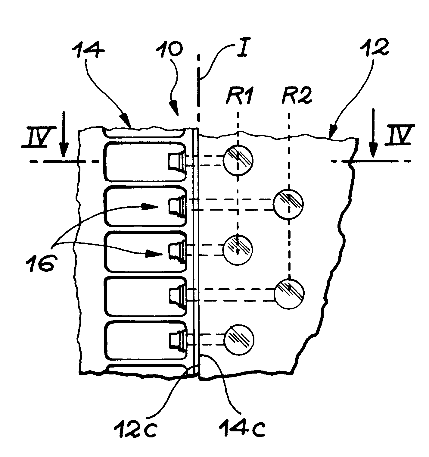
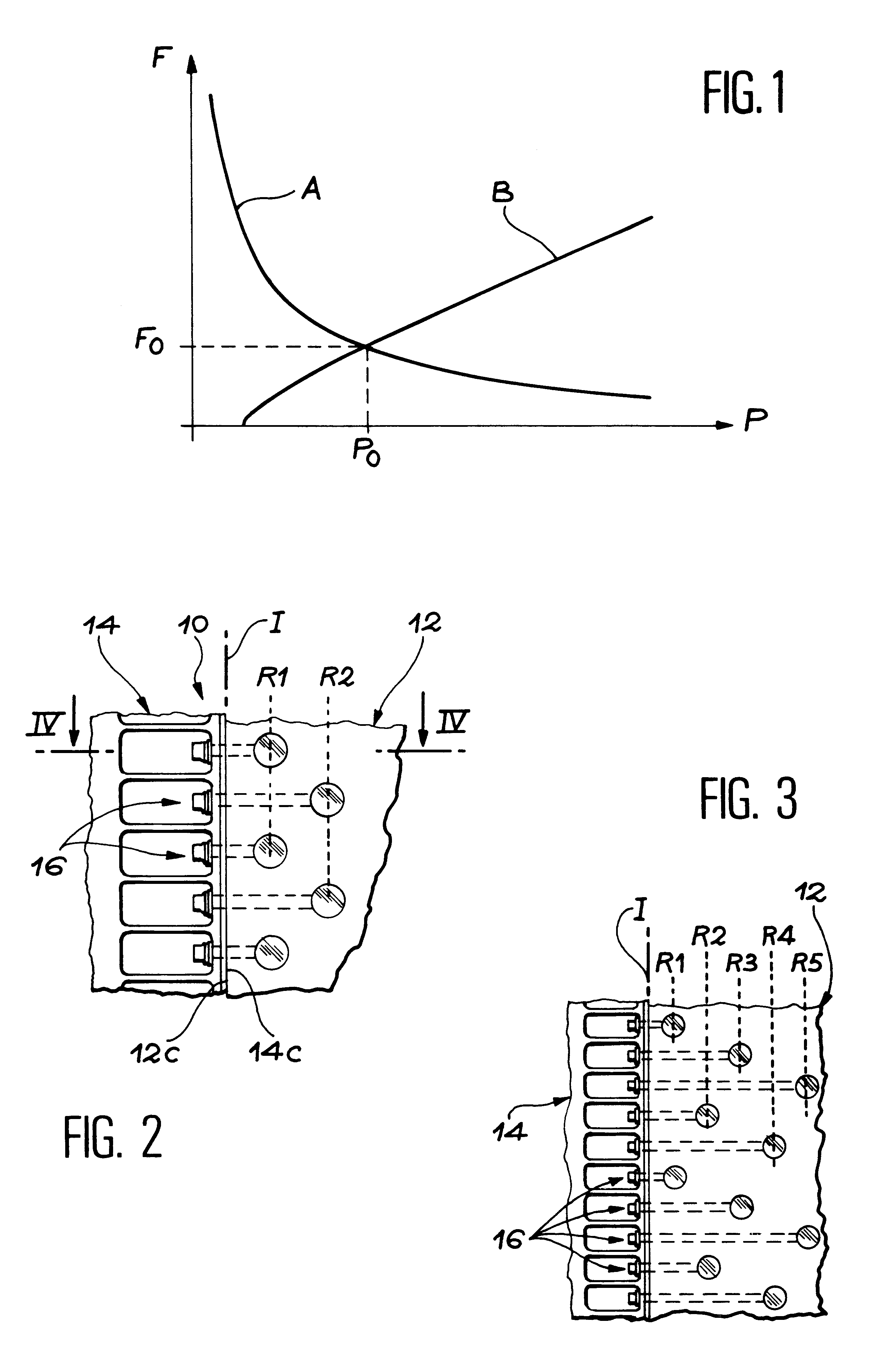
In FIG. 2, a first embodiment has been shown wherein the nuts 18 are arranged along two rows, denoted by the references R1 and R2.

second embodiment

FIG. 3 shows a second embodiment wherein the nuts 18 are arranged along five different rows, denoted by the references R1, R2, R3, R4 and R5.

For a given number of mounts 16, this arrangement in staggered rows of the nuts 18 makes it possible to increase the quantity of material between two holes 24 corresponding to two consecutive mounts. The result is less embrittlement of the panel to tensile and compressive forces. This arrangement therefore makes it possible to reduce the effective pitch of the mounts 16 and to increase proportionally the flux of forces able to be transmitted by the joint device 10.

Like FIG. 1 previously described, FIG. 6 shows an orthonormal frame in which the pitch P (in mm) between two mounts 16 has been shown as the x-coordinates and the flux F (as daN / mm) of the forces transmitted between the panel 12 and the structure 14 has been shown as the y-coordinates.

In FIG. 6 curve A reappears, showing the change in the flux able to be withstood by the tension screw...

third embodiment

variant, the tension screws 20 the nuts of which are arranged in different rows are clamped more tightly when the forces transmitted are smaller, and conversely. Pre-stressing is thus applied to the screws transmitting the smaller forces, in such a way that the forces applied to the joint device are distributed more homogeneously between the different mounts.

Furthermore, it should be noted that the forces able to be transmitted through the joint device according to the invention become larger the greater the distance separating the different rows. Indeed, the result of this is an increase in the quantity of material (and therefore in the sheared cross-section) between the holes 24 of the adjacent mounts 16, which belong to different rows. The effect of this is to delay the rupture of the composite material and to use still more the capacities of the tension screws 20, without appreciably increasing their mass. In the same spirit, an increase in the distance separating the first row ...


PUM


Abstract

A device for joining a panel and another structure.The device (10) includes a plurality of mounts (16) evenly distributed along the interface (I) between the panel (12) and the structure (14). Each mount (16) comprises a tension screw approximately perpendicular to the interface (I) and a nut embedded in the panel (12), close to the latter. To allow the transmission of more significant forces, the nuts are arranged in at least two different rows (R1, R2, R3), parallel to the interface (I). Moreover, the nuts of the adjacent mounts are located in different rows.

Description

The invention relates to a device for joining a panel and any structure, between which significant forces are to be transmitted.The invention applies in particular to the case where the panel is made of a composite material and where the structure is made of metal. However, it is not restricted to this particular case and also relates, for example, to the assembly of a metal panel and a metal structure.The joint device according to the invention may particularly be used in aeronautics, for example in order to provide the connection between the wing and the fuselage of an aircraft, between wing panels and between fuselage sections. The joint device according to the invention may also be used in the space field, for example to assemble different sections of a launcher or of its boosters. Indeed, it allows the condition of the panel surfaces and, consequently the aerodynamic properties of the assembly not to be too markedly affected.Prior ArtA usual technique of joining two parts consi...

Claims


Application Information

Patent Timeline
Patent Type & Authority Patents(United States)
IPC IPC(8): F16B5/00F16B5/02F16B5/01B64C1/12B64C3/28
CPCB64C1/12B64C3/28F16B5/0291F16B5/01Y10T403/75
Inventor BEQUET, FRANCK
Owner AIRBUS OPERATIONS (SAS)
Why Eureka
Try Eureka