System and methods for clot dissolution

Inactive Publication Date: 2003-12-16
TYCO HEALTHCARE GRP LP
View PDF76 Cites 162 Cited by
  • Summary
  • Abstract
  • Description
  • Claims
  • Application Information

AI Technical Summary

Benefits of technology

FIGS. 10A and 10B illustrate a catheter 140 comprising catheter body 142 and an inner catheter shaft 144. A proximal isolation balloon 146 is formed at the distal end of the catheter body 142. The distal isolation balloon 148 is formed at the distal end of the inner catheter body 144. Thrombolytic agent distribution ports 150 are formed over a non-linear region 152 of the inner catheter body 144. In this way, the length of the non-linear region and thrombolytic agent release region 152 can be adjusted by axially extending or retracting the inner catheter member 144 relative to the catheter body 142. In particular, balloon 146 on catheter body 142 may be anchored at a proximal end of a desired treatment region. The distal isolation balloon 148 may then be extended by a desired distance from the distal tip of the catheter body 142 to create an isolated treatment region therebetween (with both balloons being inflated). The non-linear region 152 may then be rotated with thrombolytic agent released in order to treat the clot and thrombus between the balloons. Optionally, the released emboli can be aspirated through the distal end of the cat

Problems solved by technology

Such recirculation may significantly enhance the th

Method used


Image

  • System and methods for clot dissolution
  • System and methods for clot dissolution
  • System and methods for clot dissolution

Examples


Embodiment Construction

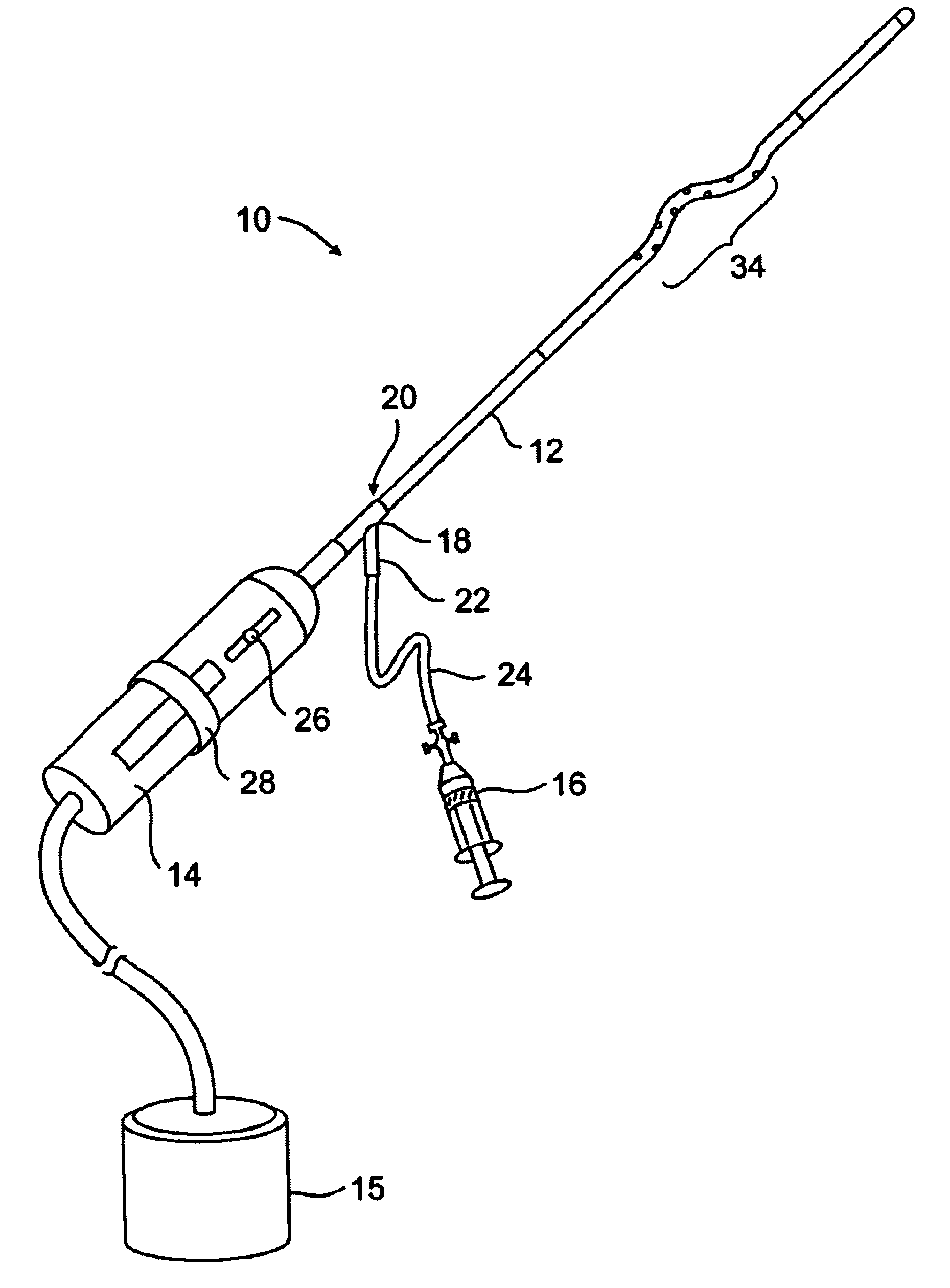
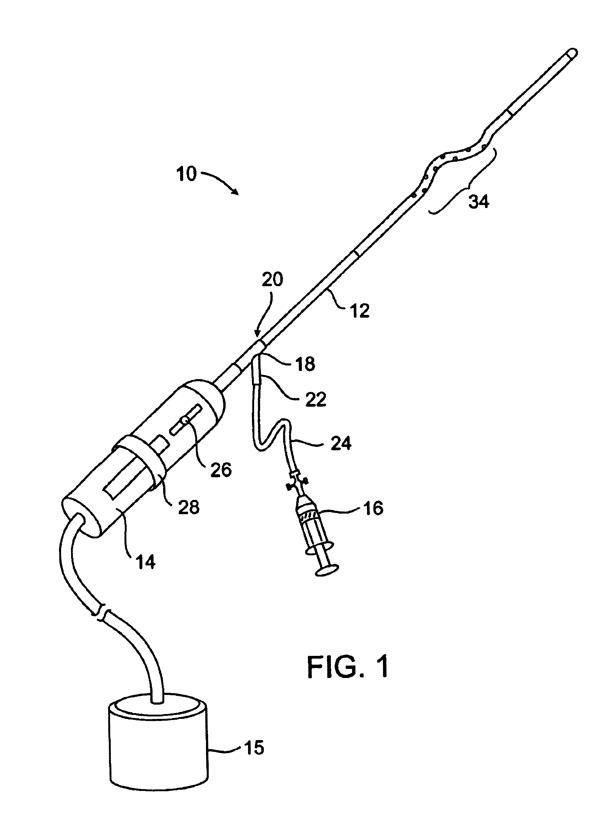
In FIG. 1, a clot disruption apparatus 10 is shown to comprise a catheter body 12, a motor drive unit 14, and a thrombolytic agent delivery device 16. The motor drive unit 14 is attached to a hub 18 at a proximal end 20 of the catheter body 12. The thrombolytic agent delivery device is shown as a syringe which is attached to a side port 22 on hub 18 through a conventional tube 24. It will be appreciated that other thrombolytic agent delivery devices could also be used, such as pumps, gravity bags, and the like. The thrombolytic agent delivered by device 16 can be any conventional bioactive agent which is capable of disrupting and dissolving clot and thrombus, such as tissue plasminogen activator (tPA), streptokinase, urokinase, heparin, low molecular weight heparin, and the like. The thrombolytic agents may be delivered through the delivery device 16 as a bolus, continuously over time, or as combinations thereof.

A motor drive unit 14 includes a sliding switch 26 which controls the r...


PUM


Abstract

Clot disruption and dissolution are achieved using a catheter having both an agitator and the ability to deliver a thrombolytic agent. The catheter is introduced to a target region with a blood vessel and the agitator manipulated to engage and disrupt a region of clot therein. The thrombolytic agent, such as tPA, streptokinase, or urokinase, is directly released into the clot at the point where the agitator is engaging the clot. In this way, the thrombolytic activity of the agent is enhanced and the dissolution of the clot is improved.

Description

1. Field of the InventionThe present invention relates generally to medical devices and methods. More particularly, the present invention relates to devices and methods for dissolving and disrupting occlusive materials from blood vessels.Thrombosis and atherosclerosis are common ailments which occur in humans and which result from the deposition of thrombus within the lumens of blood vessels. When hardened, such deposits are commonly referred to as plaque. Such deposits are most common in the peripheral blood vessels that feed the limbs of the human body and the coronary arteries which feed the heart. Stasis, incompetent valves, and trauma in the venous circulation cause thrombosis, particularly occurring as a deep vein thrombosis in the peripheral vasculature. When such deposits accumulate in localized regions of the blood vessel, they can restrict blood flow and cause a serious health risk.In addition to forming in the natural vasculature, thrombosis is a serious problem in "artif...

Claims


Application Information

Patent Timeline
IPC IPC(8): A61B17/22A61M25/00A61M25/01A61B17/00A61F2/958
CPCA61B17/22A61B17/320758A61M25/0021A61B17/320725A61M25/0105A61B2017/22084A61M25/007A61B2017/22067
Inventor EVANS, MICHAEL A.DEMARAIS, DENISE M.EVERSULL, CHRISTIAN S.LEEFLANG, STEPHEN A.
Owner TYCO HEALTHCARE GRP LP
Why Eureka
Try Eureka