Lossless coding method for waveform data

a lossless coding and waveform data technology, applied in the field of lossless coding methods for waveform data, can solve the problems of insufficient playback time of data rates occupied by audio or other waveform data in digital pcm (pulse code modulation) form, difficulty in conveying data rates of around 11.5 mbit/second with adequate playback through existing storage media such as high-density compact discs or optical storage media, etc., to preserve the integrity of quiet passages

Inactive Publication Date: 2003-12-16
DOLBY LAB LICENSING CORP
View PDF18 Cites 119 Cited by
  • Summary
  • Abstract
  • Description
  • Claims
  • Application Information

AI Technical Summary

Benefits of technology

Additionally, for low signal levels, the lossy coding will revert to being lossless since the encoded data rate in quiet passages will be sufficiently low as to require no further discarding of data. Unlike other lossy systems, this will preserve the integrity of quiet passages.
In addition, when lossy encoders according to the invention in its sixth aspect are cascaded, the degree of degradation of the original waveform will not continue

Problems solved by technology

The data rate occupied by audio or other waveform data in digital PCM (pulse code modulation) form is often too high for the transmission or storage medium used to convey waveforms.
However, in many applications, prior art methods of lossless encoding and decoding of waveform data have considerable practical problems.
When it is desired in addition to convey multichannel stereo or surround sound, one may need to convey to the user perhaps 5 or 6 channels of audio at a 96 kHz sampling rate with around 20 bit resolution, and the resulting data rates of around 11.5 Mbit/second are difficult to convey with adequate playing time via existing storage media such as high-density compact disc or optical storage media.
This makes such predictors unsuitable for coping with media having peak data read or write rate limitations.
Predictors involving non-integer coefficients can encode waveforms with much better reductions of both peak and average data rates, but unfortunately, these have the problem that an ideal

Method used


Image

  • Lossless coding method for waveform data
  • Lossless coding method for waveform data
  • Lossless coding method for waveform data

Examples


Embodiment Construction

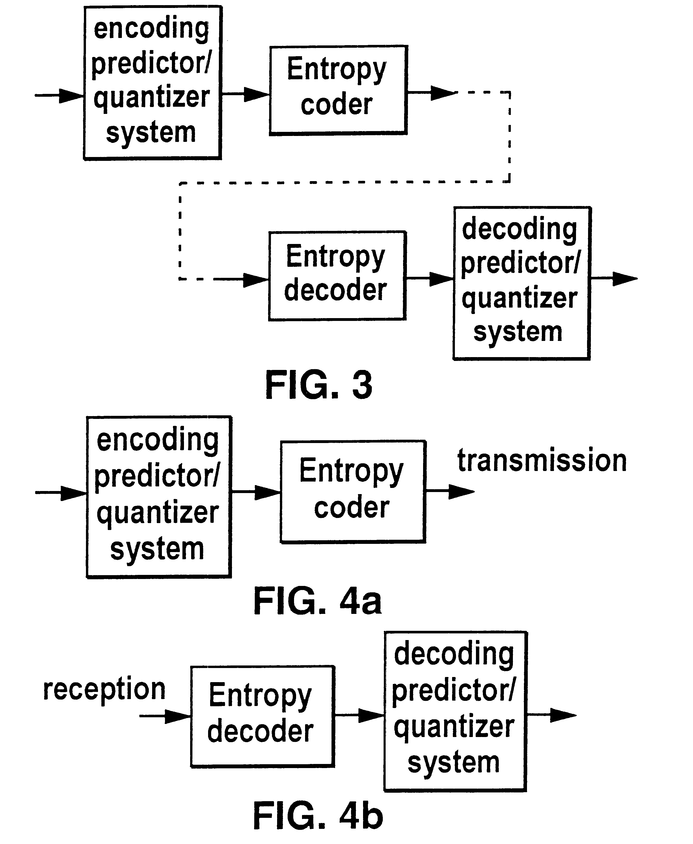
The invention may be implemented by feeding waveform data in digital PCM form into digital signal processing chips, typical current examples of which are the Motorola DSP 56000 or DSP 96000 family or the Texas Instruments TMS 320 family, and the encoding and decoding algorithms may be implemented in the form of code designed to run on the chip and stored in program memory on or associated with the chip. Alternatively, in computer based applications, the waveform signal in PCM and encoded forms may be handled as digital data in the computer and its associated memory, and the encoding and decoding algorithms implemented in the form of program code for the computer in ways well known to those skilled in the art. In applications requiring the production of large numbers of cheap encoders and decoders, the signal processing chips used may be optimised for the algorithms used to produce dedicated chips for this specific application.

Waveform signals will usually originate either from an or...


PUM


Abstract

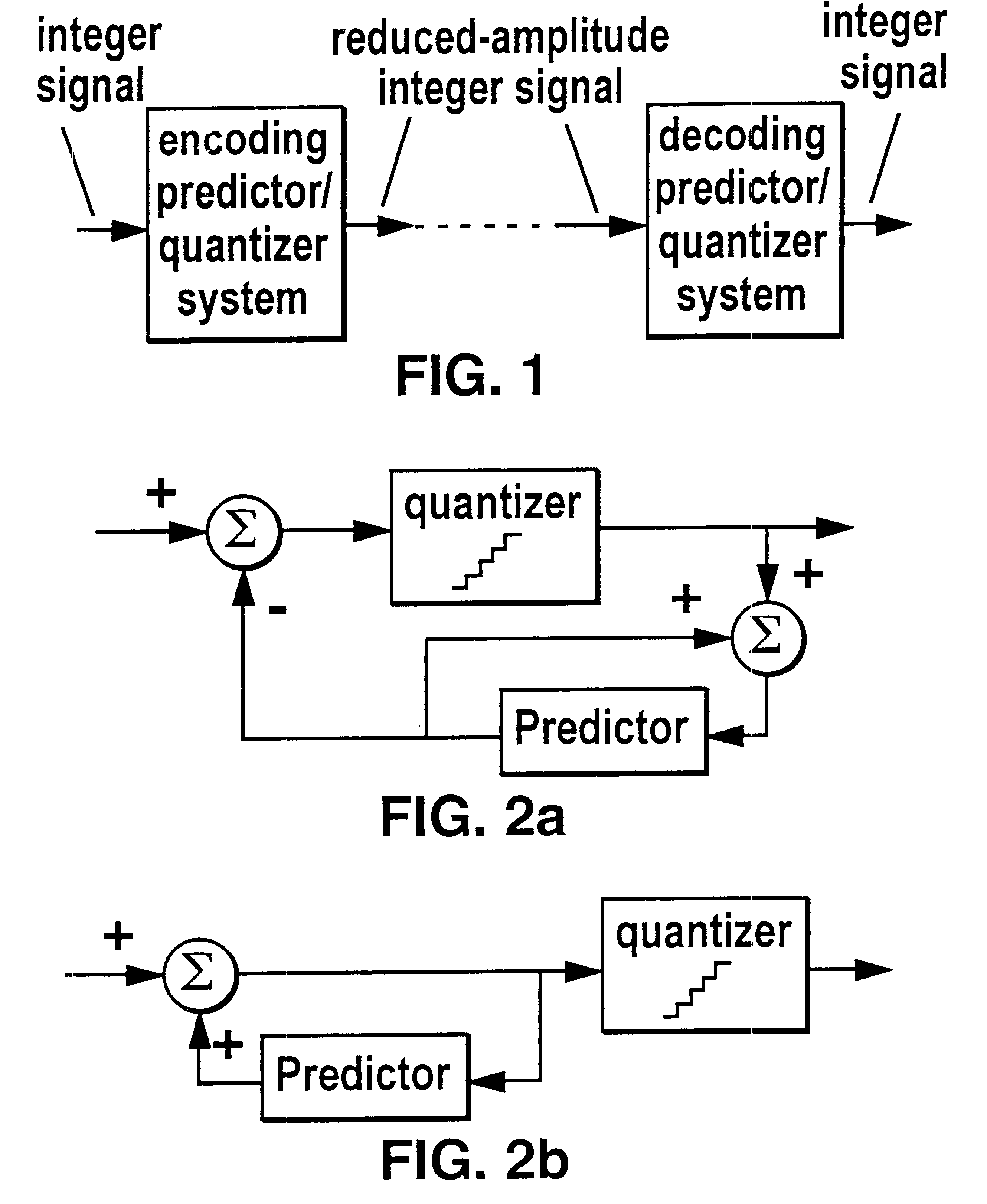
In a method of lossless processing of an integer value signal in a prediction filter which includes a quantiser, a numerator of the prediction filter is implemented prior to the quantiser and a denominator of the prediction filter is implemented recursively around the quantiser to reduce the peak data rate of an output signal. In the lossless processor, at each sample instant, an input to the quantiser is jointly responsive to a first sample value of a signal input to the prediction filter, a second sample value of a signal input to the prediction filter at a previous sample instant, and an output value of the quantiser at a previous sample incident. In a preferred embodiment, the prediction filter includes noise shaping for affecting the output of the quantiser.

Description

This invention relates to the lossless coding and decoding of waveform data so as to reduce the required data rate without any alteration of the decoded waveform data, particularly the use of lossless prediction and matrixing methods with particular regard to those using finite precision non-integer arithmetic unaffected by rounding errors and to applications in audio and image waveform coding and decoding.The data rate occupied by audio or other waveform data in digital PCM (pulse code modulation) form is often too high for the transmission or storage medium used to convey waveforms. Methods of reducing waveform data rate are known in the prior art and may be classified into two types, lossy and lossless coding. Lossy coding discards or alters the waveform data in a way which is small in relation to the requirement of how the data is used, whereas lossless coding reduces the data rate by eliminating signal redundancies in coded form, but in a way that allows the exact original data...

Claims


Application Information

Patent Timeline
IPC IPC(8): H03M7/38H04B14/06H03M7/30
CPCH03M7/3046
Inventor CRAVEN, PETER G.GERZON, MICHAEL A.
Owner DOLBY LAB LICENSING CORP
Why Eureka
Try Eureka