Planar light source system and light deflecting device therefor

a light source and light deflector technology, applied in the direction of lighting and heating equipment, instruments, machines/engines, etc., can solve the problems of reducing the thickness reducing the weight of the light source portion, and not meeting the requirements of low power consumption and high luminan

Inactive Publication Date: 2003-12-30
MITSUBISHI RAYON CO LTD
View PDF16 Cites 149 Cited by
  • Summary
  • Abstract
  • Description
  • Claims
  • Application Information

AI Technical Summary

Benefits of technology

Therefore, an object of the present invention is to provide a planar light source system which is suitably used as a planar light source system using a substantially point-shaped light source such as an LED light source or the like for use in a liquid crystal display device for mobile electronic equipment such as a cellular phone, a portable information terminal or personal digital assistant, an electronic organizer, a game machine, a note type personal computer or the like, and low in power consumption, compact in size, excellent in light utilization efficiency, high in luminance and excellent in luminance uniformity, and a light deflection device used in the planar light source system.

Problems solved by technology

With respect to the under-lighting type back light source, it is difficult to reduce the weight of the light source portion and also reduce the thickness of the light source portion, and also there occurs a see-through phenomenon that fluorescent lamps or the like used as a light source are seen through a display panel.
In such a planar light source system, the distribution of the emission light excessively expands, particularly in the vertical and parallel directions (more particularly, in the parallel direction) to the light source, and thus it does not sufficiently satisfy the requirements for low power consumption and high luminance.
However, since the linear prism extending straightly is formed in parallel to the light incident edge, light emitted from the LED light source in a slant direction cannot be directed in the normal direction of the light emission face of the light guide, so that an area located in the slant direction is dark and thus luminance unevenness occurs.
However, it is impossible for the formation of such a diffusion pattern to efficiently emit light propagating through the light guide in the normal direction of the light emission face of the light guide, so that sufficient luminance cannot be achieved.
However, according to these planar light source system, emission light from the light guide is emitted directly or through a light diffusion film, and the distribution of emission light from the planar light source system has low directionality, so that a planar light source system having high luminance cannot be achieved.
However, according to this planar light source system, it is difficult to efficiently emit directional light emitted from an LED light source in the normal direction, and also the distribution of emission light is excessively expanded, so that the luminance in the normal direction and the light utilization efficiency are lowered.
If this angle is smaller than this range, the deflecting action of light by refraction is generally insufficient.
However, it is difficult to form arc-shaped elongated prisms 16 each having an accurate shape, and thus the elongated prisms are preferably formed continuously in the circumferential direction of the arc.
If the light emission pattern in the direction b is excessively wide, the light is liable to be emitted in the neighborhood of the primary light source 1, and there is a tendency to reduce the uniformity of luminance.
On the other hand, if the light emission pattern in the direction b is excessively narrow, the emission rate of the emission light from the light guide 2 is small, and thus there is a tendency to reduce the luminance.
If the pitch is excessively small, it is difficult to design the elongated lenses in an accurate shape so that the incident light is efficiently expanded in the light guide, and thus desired performance cannot be achieved.
On the other hand, if the average slant angle .theta.a of the roughened surface exceeds 8 degrees, destruction of the shape of the elongated lenses is intensified, so that the directional light emission characteristic of the elongated lenses is lost or the emission light amount in the neighborhood of the light incident end surface is excessively increased, resulting a tendency to lose uniformity of luminance.

Method used


Image

  • Planar light source system and light deflecting device therefor
  • Planar light source system and light deflecting device therefor
  • Planar light source system and light deflecting device therefor

Examples


example 2

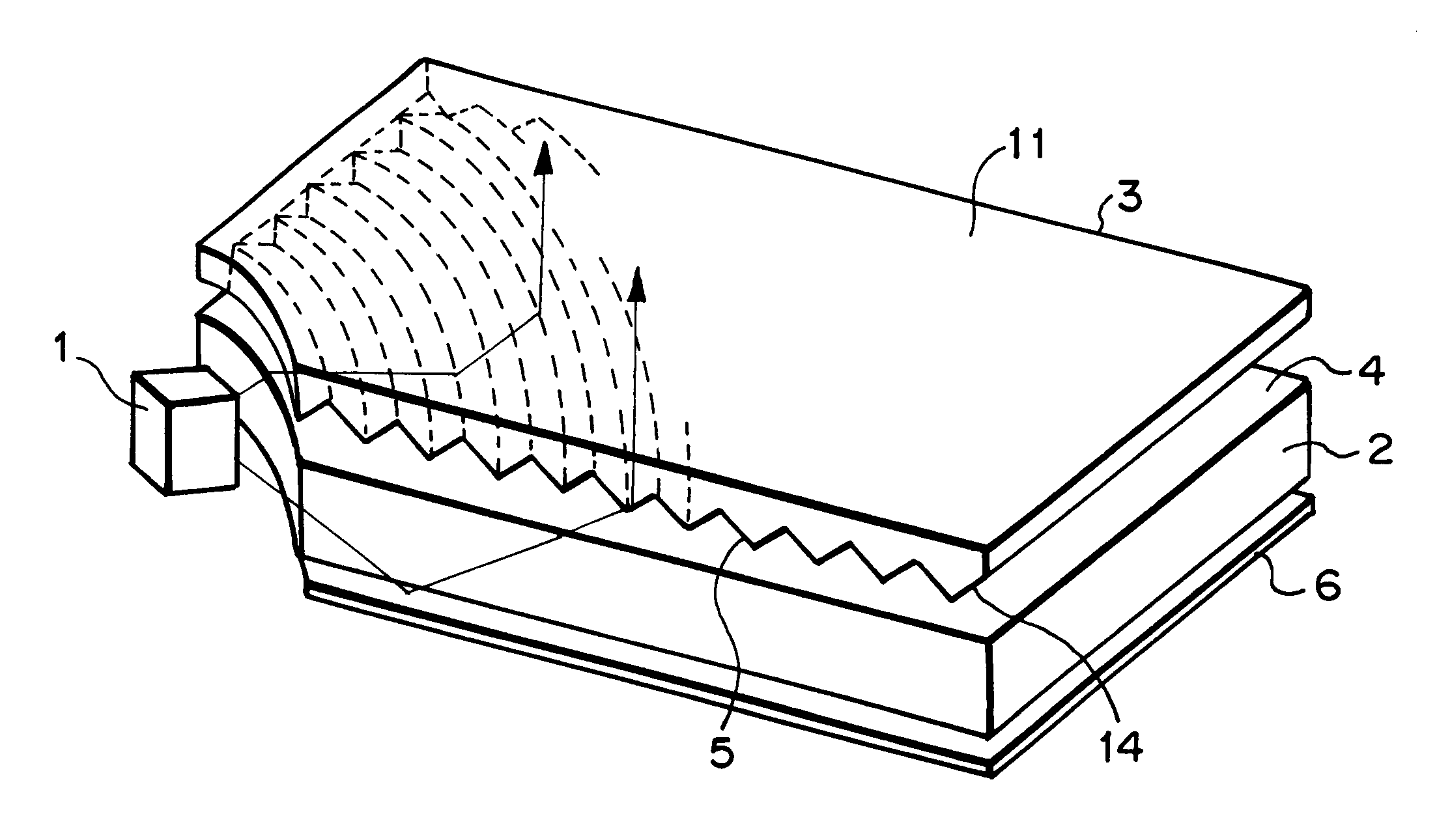
A blast treatment using glass beads of 53 .mu.m or less in particle size (FGB-400 produced by Fuji Manufacturing Works Co., Ltd.) was carried out on an effective area Z of 40 mm.times.30 mm on the surface of a mirror-polished SUS plate of 48 mm.times.34 mm in square and 3 mm in thickness under a blast pressure of 1.0 kgf / cm.sup.2 while the distance from the SUS plate to a blast nozzle was set to 40 cm, thereby achieving a roughened-surface metal mold. Injection molding was carried out by using the roughened-surface metal mold thus achieved and the metal mold used in Example 1 on which the arc-shaped prism pattern was formed to achieve a rectangular light guide of 48 mm in long side length, 34 mm in short side length and 0.8 mm in thickness. Polymethylmethacrylate was used as the material of the injection molding.

In the light guide thus achieved, one surface thereof had a roughened surface having an average slant angle of 0.6 degree, and the arc-shaped prism pattern was formed on the...

example 3

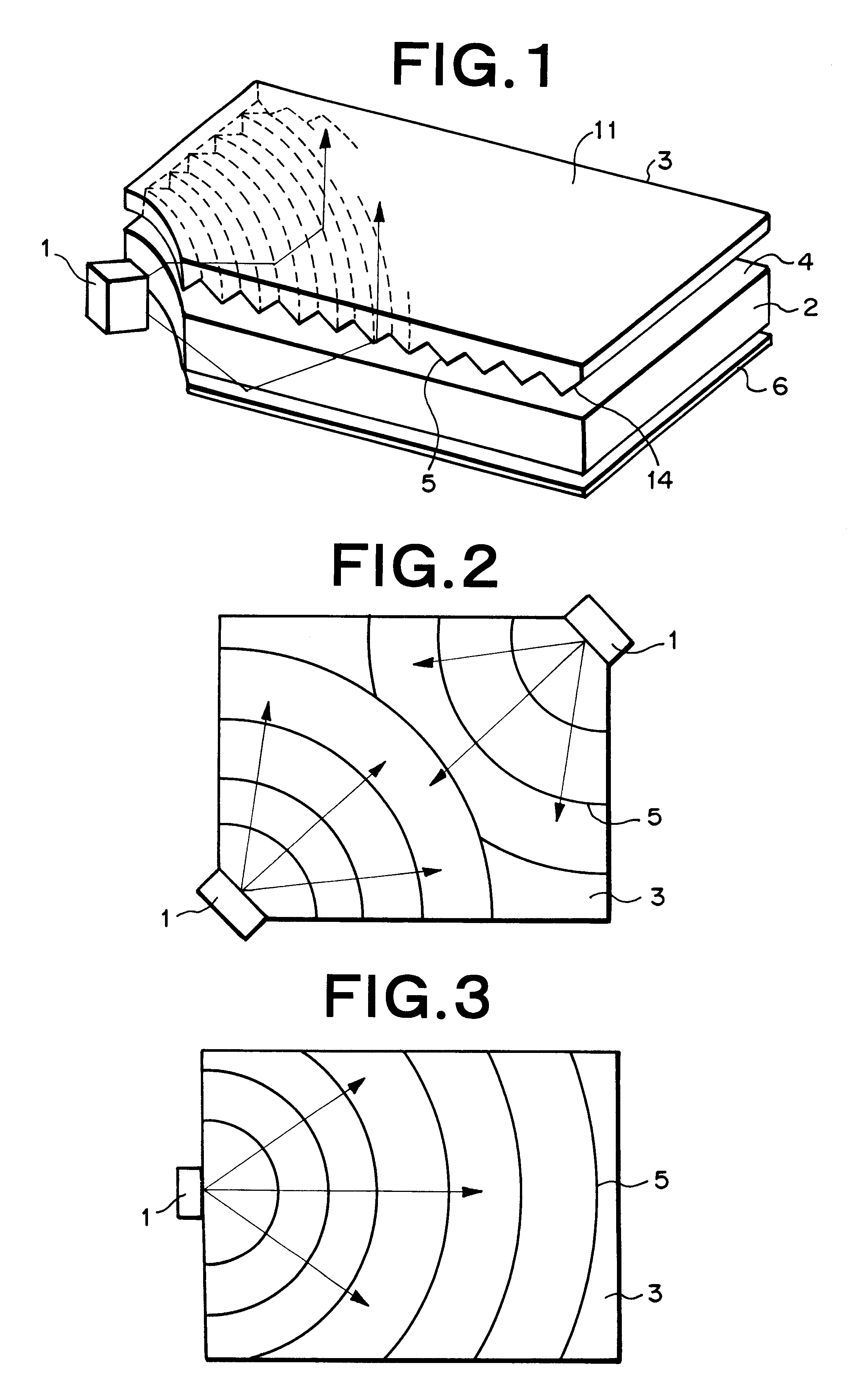
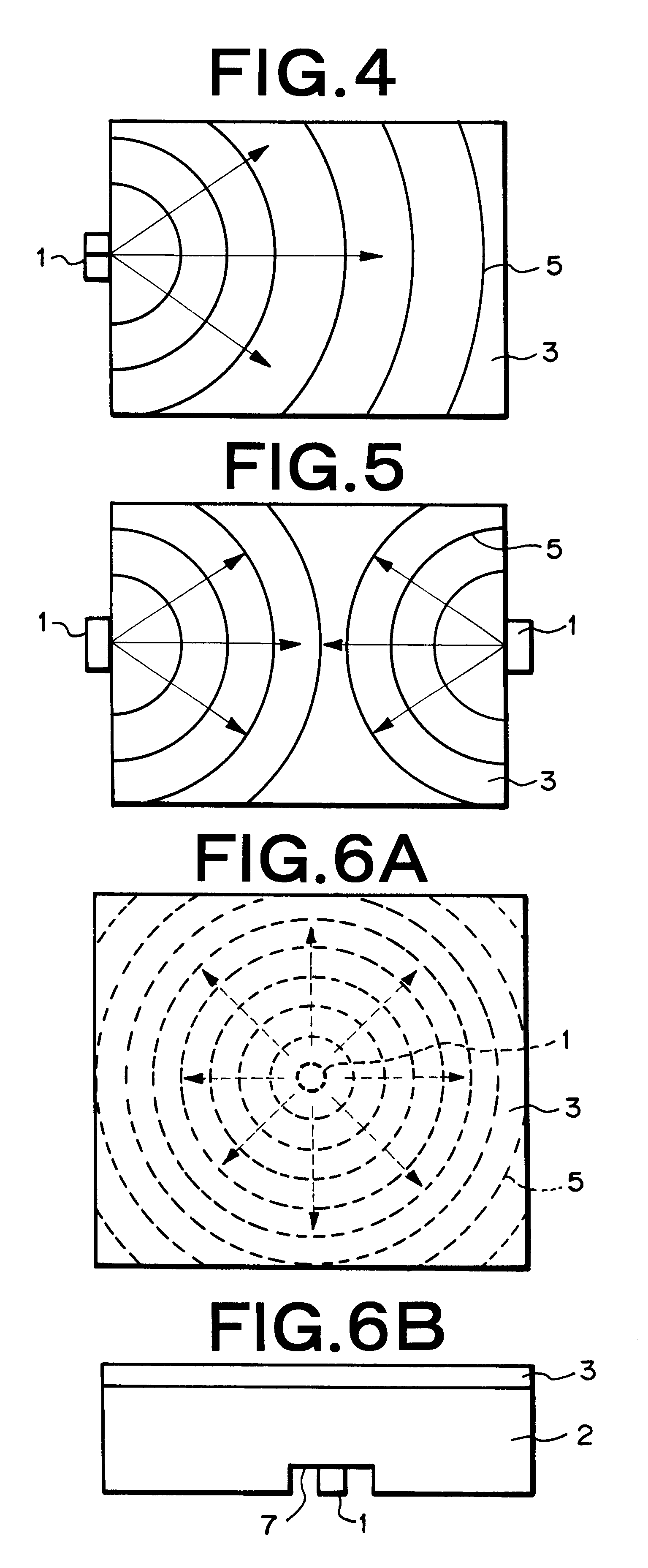
Radially elongated prisms each having an isosceles triangular cross section with an apex angle of 130 degrees were formed at an angular pitch of 30 degrees outside an effective area Z of 40 mm.times.30 mm on the mirror-polished surface of a brass plate of 48 mm.times.34 mm in square and 3 mm in thickness by cutting work so that they extend in the radial direction with the neighborhood of one corner of the rectangle of 48 mm.times.34 mm positioned at the center, thereby forming a metal mold having a radially elongated prism pattern. By using the metal mold having the radially elongated prism pattern thus achieved and the metal mold having the arc-shaped elongated prism pattern used in Example 1, injection molding was performed so that the center of the radially elongated prism pattern was coincident with the center of the arc-shaped prism pattern, and a rectangular light guide plate of 48 mm in long side length, 34 mm in short side length and 0.8 mm in thickness. Polymethylmethacryla...


PUM

PropertyMeasurementUnit
intersecting angleaaaaaaaaaa
refractive indexaaaaaaaaaa

Abstract

A planar light source system having an LED (1) serving as a primary light source of substantially point-shaped light source, a light guide (2) having a light incident face on which light emitted from the LED (1) is incident and a light emission face (4) from which light guided through the light guide (2) is emitted, a light deflecting device (3) for controlling the direction of the emission light from the light guide (2), and a reflection sheet (6). LED (1) is disposed at a corner portion of the light guide (2), and many elongated prisms (5) are arranged substantially arcuately in parallel to each other on the light incident surface (14) of the light deflecting device (3) so as to surround LED (1).

Description

The present invention relates to a planar light source system using a substantially point-shaped light source such as an LED light source or the like used for a liquid crystal display device or the like, and particularly to a planar light source system which is used for mobile electronic equipment such as a cellular phone, a portable information terminal or personal digital assistant (PDA), an electronic organizer, a game machine, a note type personal computer or the like and is designed to be enhanced in miniaturization and reduced in power consumption, and a light deflecting device used therefor.DESCRIPTION OF THE RELATED ARTDemands for mobile electronic equipment such as a cellular phone, a portable information terminal or personal digital assistant, an electronic organizer, a game machine, a note type personal computer, etc. has been recently enhanced, and a light source which is reduced in power consumption and designed to have a thin body and also provides high and uniform lum...

Claims


Application Information

Patent Timeline
Patent Type & Authority Patents(United States)
IPC IPC(8): F21V8/00G02B5/04G02B6/00F21Y101/02G02B5/02G02F1/13357
CPCG02B5/045G02B6/0061G02B6/0038G02B6/0036G02B6/0021G02F1/1335
Inventor YAMASHITA, TOMOYOSHIHAYASHI, YASUKOCHIBA, ISSEI
Owner MITSUBISHI RAYON CO LTD
Why Eureka
Try Eureka